Ch. 30 - Inductance, Electromagnetic Oscillations, and AC Circuits
Giancoli Douglas - Physics for Scientists and Engineers 5th edition
Giancoli Douglas5th editionPhysics for Scientists and EngineersISBN: 9780137488179Non è quello che usi tu?Cambia libro di testo
Capitolo 29, Problema 90

Suppose a series LRC circuit has two resistors, R₁ and R₂, two capacitors, C₁ and C₂, and two inductors, L₁ and L₂ all in series. Calculate the total impedance of the circuit.

Guida verificata passo dopo passo
1
Start by understanding that the total impedance (Z) in a series LRC circuit is the sum of the individual impedances of the resistors, capacitors, and inductors. Impedance is a complex quantity, combining resistance (real part) and reactance (imaginary part).
Write the impedance for each component: Resistors have purely real impedance, so Z₁ = R₁ and Z₂ = R₂. Capacitors have an impedance given by Z_C = -i/(ωC), where ω is the angular frequency (ω = 2πf), and inductors have an impedance given by Z_L = iωL.
Calculate the total impedance of the resistors: Since the resistors are in series, their total impedance is Z_R = R₁ + R₂.
Calculate the total impedance of the capacitors: Since the capacitors are in series, their combined impedance is Z_C = 1 / (1/Z_C₁ + 1/Z_C₂). Substitute Z_C₁ = -i/(ωC₁) and Z_C₂ = -i/(ωC₂) into this formula.
Calculate the total impedance of the inductors: Since the inductors are in series, their total impedance is Z_L = iωL₁ + iωL₂. Finally, sum up the total impedance of the resistors, capacitors, and inductors to get the total impedance of the circuit: Z_total = Z_R + Z_C + Z_L.

Risposta video verificata per un problema simile:

Questa soluzione video è stata consigliata dai nostri tutor come utile per risolvere questo problema.
Durata del video:
7m

Concetti chiave

Ecco i concetti essenziali che devi comprendere per rispondere correttamente alla domanda.

Impedance in AC Circuits

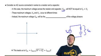
Impedance is the total opposition that a circuit offers to the flow of alternating current (AC) and is represented as a complex number. It combines resistance (R) and reactance (X), where reactance arises from capacitors and inductors. The formula for total impedance (Z) in a series circuit is Z = R + jX, where j is the imaginary unit.
Video consigliato:
Percorso guidato
08:40
Impedance in AC Circuits

Series Circuit Configuration

In a series circuit, components are connected end-to-end, so the same current flows through each component. The total impedance in a series circuit is the sum of the individual impedances of each component. This means that the total resistance and reactance can be calculated by simply adding the respective values of resistors, capacitors, and inductors.
Video consigliato:
Percorso guidato
05:55
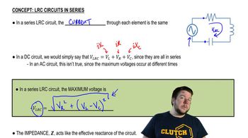
LRC Circuits in Series

Reactance of Capacitors and Inductors

Reactance is the opposition to AC due to capacitors and inductors. Capacitive reactance (X_C) decreases with increasing frequency and is given by X_C = 1/(ωC), while inductive reactance (X_L) increases with frequency and is given by X_L = ωL, where ω is the angular frequency. In a series LRC circuit, the total reactance is the difference between inductive and capacitive reactance, X = X_L - X_C.
Video consigliato:
Percorso guidato
03:36
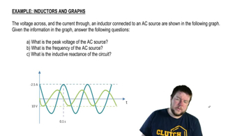
Inductors and Graphs
Pratica correlata
Domanda del libro di testo

In some experiments, very tiny distances or spaces ( ≈ nm ) can be measured by using capacitance. Consider forming an LC circuit using a parallel-plate capacitor with plate area A, and a known inductance L. If f is on the order of 1 MHz and can be measured to a precision of ∆f = 1 Hz, with what percent accuracy can x be determined? Assume fringing effects at the capacitor’s edges can be neglected.

830
views
Domanda del libro di testo

In a plasma globe, a hollow glass sphere is filled with low-pressure gas and a small spherical metal electrode is located at its center. Assume an ac voltage source of peak voltage Vo and frequency f is applied between the metal sphere and the ground, and that a person is touching the outer surface of the globe with a fingertip, whose approximate area is 1.0 cm². The equivalent circuit for this situation is shown in Fig. 30–36, where RG and RP are the resistances of the gas and the person, respectively, and C is the capacitance formed by the gas, glass, and finger. (a) Determine C assuming it is a parallel-plate capacitor. The conductive gas and the person’s fingertip form the opposing plates of area A = 1.0 cm². The plates are separated by glass (dielectric constant K = 5.0) of thickness d = 2.0 mm. (b) In a typical plasma globe, f = 12 kHz. Determine the reactance XC of C at this frequency in MΩ. (c) The voltage may be Vo = 2500 V. With this high voltage, the dielectric strength of the gas is exceeded and the gas becomes ionized. In this “plasma” state, the gas emits light (“sparks”) and is highly conductive so that RG << XC. Assuming also that RP << XC, estimate the peak current that flows in the given circuit. Is this level of current dangerous? (d) If the plasma globe operated at f = 1.0 MHz, estimate the peak current that would flow in the given circuit. Is this level of current dangerous?


<IMAGE>

91
views
Domanda del libro di testo

The RC circuit shown in Fig. 30–39 is a low-pass filter because it passes low-frequency ac signals with less attenuation than high-frequency ac signals. (a) Show that the voltage gain is A=Vout/Vin=1/(4π2f2R2C2+1)12A = V_{\(\text{out}\)}/V_{\(\text{in}\)} = 1/(4\(\pi\)^2 f^2 R^2 C^2 + 1)^{\(\frac{1}{2}\)} (b) Discuss the behavior of the gain A for f → 0 and f → ∞.

1384
views
Domanda del libro di testo

Show that if the inductor L in the filter circuit of Fig. 30–33 (Problem 87) is replaced by a large resistor R, there will still be significant attenuation of the ac voltage and little attenuation of the dc voltage if the input dc voltage is high and the current (and power) are low.

1511
views
Domanda del libro di testo

For the circuit shown in Fig. 30–35, show that if the condition R₁ R₂ = L/C is satisfied then the potential difference between points a and b is zero for all frequencies.

1068
views
Domanda del libro di testo

Filter circuit. Figure 30–33 shows a simple filter circuit designed to pass dc voltages with minimal attenuation and to remove, as much as possible, any ac components (such as 60-Hz line voltage that could cause hum in an audio system, for example). Assume Vin = V1 + V2 where V1 is dc and V2 = V20 sin ωt, and that any resistance is very small. (a) Determine the current through the capacitor: give amplitude and phase (assume R = 0 and XL > XC). (b) Show that the ac component of the output voltage, V2out, equals (Q/C) - V1 where Q is the charge on the capacitor at any instant, and determine the amplitude and phase of V2out (c) Show that the attenuation of the ac voltage is greatest when XC << XL, and calculate the ratio of the output to input ac voltage in this case. (d) Compare the dc output voltage to input voltage.

106
views