Ch. 26 - DC Circuits
Giancoli Douglas - Physics for Scientists and Engineers 5th edition
Giancoli Douglas5th editionPhysics for Scientists and EngineersISBN: 9780137488179당신이 사용하는 게 아니라요?교과서 변경
25장, 문제 58a

A galvanometer has an internal resistance of 32 Ω and deflects full scale for a 48-μA current. Describe how to use this galvanometer to make an ammeter to read currents up to 25 A.

검증된 단계별 안내
1
Understand the problem: A galvanometer is a sensitive device that measures small currents. To convert it into an ammeter capable of measuring larger currents (up to 25 A), we need to add a shunt resistor in parallel with the galvanometer. This shunt resistor will bypass most of the current, allowing only a small fraction to pass through the galvanometer.
Step 1: Calculate the voltage across the galvanometer when it is at full-scale deflection. Use Ohm's Law: \( V_g = I_g \cdot R_g \), where \( I_g = 48 \mu A \) (full-scale current) and \( R_g = 32 \Omega \) (internal resistance of the galvanometer).
Step 2: Determine the current that needs to bypass the galvanometer. The total current to be measured is \( I = 25 \, A \), so the current through the shunt resistor is \( I_s = I - I_g \).
Step 3: Use the fact that the voltage across the galvanometer and the shunt resistor must be the same (since they are in parallel). The voltage across the shunt resistor is \( V_s = I_s \cdot R_s \), where \( R_s \) is the resistance of the shunt resistor. Set \( V_g = V_s \) and solve for \( R_s \): \( R_s = \frac{V_g}{I_s} \).
Step 4: Substitute the values of \( V_g \), \( I_g \), and \( I_s \) into the equation for \( R_s \) to calculate the required shunt resistance. This will give you the value of the resistor needed to convert the galvanometer into an ammeter capable of measuring up to 25 A.

비슷한 문제에 대한 검증된 영상 답변:

이 영상 해법은 위 문제에 도움이 된다고 튜터들이 추천한 것입니다.
영상 길이:
9m
도움이 되었나요?

주요 개념

질문에 올바르게 답하기 위해 반드시 이해해야 하는 핵심 개념들은 다음과 같습니다.

Galvanometer

A galvanometer is an electromechanical device used to detect and measure small electric currents. It operates by using a coil of wire that experiences a magnetic field, causing it to rotate and indicate the current level on a scale. The full-scale deflection of a galvanometer occurs at a specific current, which is crucial for its calibration and use in other applications.

Shunt Resistor

A shunt resistor is a low-resistance component connected in parallel with a galvanometer to allow most of the current to bypass the galvanometer. This enables the galvanometer to measure larger currents without being damaged. The value of the shunt resistor is calculated based on the maximum current desired and the full-scale deflection current of the galvanometer.
추천 영상:
가이드 코스
04:11
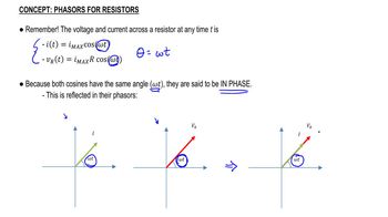
Phasors for Resistors

Current Division

Current division is a principle used in electrical circuits to determine how current is distributed among parallel branches. In the context of using a galvanometer as an ammeter, the total current entering the circuit is divided between the galvanometer and the shunt resistor. Understanding current division is essential for calculating the appropriate shunt resistance needed to ensure accurate readings at higher currents.
추천 영상:
가이드 코스
05:38
Intro to Current
관련 실천
교과서 질문

(III) Determine the net resistance in Fig. 26–61 (a) between points a and c, and (b) between points a and b. Assume R' ≠ R. [Hint: Apply an emf between the two points in each case and determine currents; use symmetry at junctions.]

113
views

교과서 질문

A galvanometer has a sensitivity of 45kΩ/V and internal resistance 20.0 Ω. How could you make this into an ammeter that reads 1.0 A full scale?

809
views
교과서 질문

(II) Suppose two batteries, with unequal emfs of 2.00 V and 3.00 V, are connected as shown in Fig. 26–63. If each internal resistance is r = 0.350Ω and R = 4.00Ω, what is the voltage across the resistor R?

803
views
교과서 질문

A galvanometer has an internal resistance of 32 Ω and deflects full scale for a 48-μA current. Describe how to use this galvanometer to make a voltmeter to give a full scale deflection of 250 V.

848
views
교과서 질문

In the circuit shown in Fig. 26–75, the 33-Ω resistor dissipates 0.80 W. What is the battery voltage?

1309
views
교과서 질문

The performance of the starter circuit in a car can be significantly degraded by a small amount of corrosion on a battery terminal. Figure 26–88a depicts a properly functioning circuit with a battery (12.5-V emf, 0.02-Ω internal resistance) attached via corrosion-free cables to a starter motor of resistance Rs = 0.15Ω. Sometime later, corrosion between a battery terminal and a starter cable introduces an extra series resistance of only RC = 0.10Ω into the circuit as suggested in Fig. 26–88b. Let P0 be the power delivered to the starter in the circuit free of corrosion, and let P be the power delivered to the starter with corrosion. Determine the ratio P/P0.

955
views