
Ch. 26 - DC Circuits
Giancoli Douglas - Physics for Scientists and Engineers 5th edition
Giancoli Douglas5th editionPhysics for Scientists and EngineersISBN: 9780137488179당신이 사용하는 게 아니라요?교과서 변경
25장, 문제 95

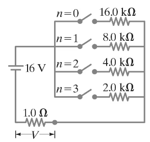
The circuit shown in Fig. 26–89 is a primitive 4-bit digital-to-analog converter (DAC). In this circuit, to represent each digit (2n) of a binary number, a “1” has the nᵗʰ switch closed whereas zero (“0”) has the switch open. For example, 0010 is represented by closing switch n = 1, while all other switches are open. Show that the voltage V across the 1.0 - Ω resistor for the binary numbers 0001, 0010, 0100, and 1010 (which represent 1, 2, 4, 10) follows the pattern that you expect for a 4-bit DAC.


검증된 단계별 안내
1
Step 1: Understand the circuit configuration. The circuit is a 4-bit digital-to-analog converter (DAC) where each switch corresponds to a binary digit (bit). When a switch is closed, it connects a voltage source to the circuit, contributing a current proportional to the bit's weight (2ⁿ). The total current through the 1.0-Ω resistor determines the output voltage V, as per Ohm's Law (V = IR).
Step 2: Analyze the contribution of each bit. Each bit corresponds to a specific current contribution based on its weight. For example, the least significant bit (LSB, n=0) contributes a current of I₀ = V₀/2⁰, the next bit (n=1) contributes I₁ = V₀/2¹, and so on. The total current is the sum of the contributions from all closed switches.
Step 3: Calculate the output voltage for each binary number. For 0001, only the LSB (n=0) is closed, so the current is I = V₀/2⁰. For 0010, only the n=1 switch is closed, so the current is I = V₀/2¹. For 0100, only the n=2 switch is closed, so the current is I = V₀/2². For 1010, the n=1 and n=3 switches are closed, so the current is I = V₀/2¹ + V₀/2³.
Step 4: Use Ohm's Law to find the voltage across the 1.0-Ω resistor. Since V = IR and the resistor has a resistance of 1.0 Ω, the voltage V is numerically equal to the total current I. For each binary number, substitute the calculated current into V = I to find the corresponding voltage.
Step 5: Verify the pattern. Observe that the output voltage V is proportional to the decimal value of the binary number. For example, 0001 (decimal 1) produces a voltage proportional to 1, 0010 (decimal 2) produces a voltage proportional to 2, and so on. This confirms the expected behavior of a 4-bit DAC, where the output voltage is directly proportional to the binary input value.

비슷한 문제에 대한 검증된 영상 답변:

이 영상 해법은 위 문제에 도움이 된다고 튜터들이 추천한 것입니다.
영상 길이:
10m
도움이 되었나요?

주요 개념

질문에 올바르게 답하기 위해 반드시 이해해야 하는 핵심 개념들은 다음과 같습니다.

Digital-to-Analog Conversion

Digital-to-Analog Conversion (DAC) is the process of converting digital signals, typically binary numbers, into analog voltages. In a 4-bit DAC, each bit represents a power of two, allowing for 16 distinct voltage levels. The configuration of switches in the circuit determines which bits are active, thus influencing the output voltage across a load, such as a resistor.

Binary Number Representation

Binary number representation uses two symbols, 0 and 1, to express values. Each digit in a binary number corresponds to a power of two, where the rightmost digit represents 2^0, the next 2^1, and so on. In the context of the DAC, the closed switches represent '1's, contributing to the total voltage output, while open switches represent '0's, contributing nothing.

Voltage Division in Circuits

Voltage division is a fundamental principle in electrical circuits where the total voltage across a series of resistors is divided among them based on their resistance values. In the DAC circuit, the output voltage across the 1.0-Ω resistor is determined by the configuration of the closed switches, which effectively creates a voltage divider that reflects the binary input as an analog voltage.
관련 실천
교과서 질문

Measurements made on circuits that contain large resistances can be confusing. Consider a circuit powered by a battery ε = 15.000 V with a 10.00-MΩ resistor in series with an unknown resistor R. As shown in Fig. 26–92, a particular voltmeter reads V1 = 366 mV when connected across the 10.00 -MΩ resistor and this meter reads V2 = 7.317 V when connected across R. Determine the value of R. [Hint: Define RV as the voltmeter’s internal resistance.]


711
views
교과서 질문

Consider two unequal resistors, of resistance R1 and R2, that are connected either in series or in parallel. Fill in the Table below assuming the electric potential on the low-voltage end of the combination is VA volts and the potential at the high-voltage end of the combination is VB volts. First draw diagrams.


665
views
교과서 질문

A galvanometer has an internal resistance of 32 Ω and deflects full scale for a 48-μA current. Describe how to use this galvanometer to make a voltmeter to give a full scale deflection of 250 V.

848
views
교과서 질문

In the circuit shown in Fig. 26–75, the 33-Ω resistor dissipates 0.80 W. What is the battery voltage?

1309
views
교과서 질문

The performance of the starter circuit in a car can be significantly degraded by a small amount of corrosion on a battery terminal. Figure 26–88a depicts a properly functioning circuit with a battery (12.5-V emf, 0.02-Ω internal resistance) attached via corrosion-free cables to a starter motor of resistance Rs = 0.15Ω. Sometime later, corrosion between a battery terminal and a starter cable introduces an extra series resistance of only RC = 0.10Ω into the circuit as suggested in Fig. 26–88b. Let P0 be the power delivered to the starter in the circuit free of corrosion, and let P be the power delivered to the starter with corrosion. Determine the ratio P/P0.

955
views