Ch. 28 - Sources of Magnetic Field
27์žฅ, ๋ฌธ์ œ 38

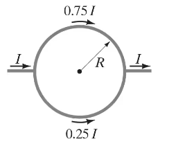
(II) A circular conducting ring of radius ๐‘… is connected to two exterior straight wires at two ends of a diameter (Fig. 28โ€“47). The current I splits into unequal portions as shown (unequal resistance) while passing through the ring. What is Bโ†’\(\overrightarrow{B}\) at the center of the ring?


๊ฒ€์ฆ๋œ ๋‹จ๊ณ„๋ณ„ ์•ˆ๋‚ด
1
Understand the problem: The circular conducting ring has a current I flowing through it, splitting into unequal portions due to unequal resistance. We need to calculate the magnetic field B at the center of the ring caused by the current distribution.
Recall the Biot-Savart Law: The magnetic field at a point due to a current element is given by: B=ฮผ0I4ฯ€dLrsinฮธ, where ฮผโ‚€ is the permeability of free space, I is the current, dL is the length of the current element, r is the distance from the element to the point, and ฮธ is the angle between dL and r.
Analyze the symmetry: The ring is circular, and the current flows through it symmetrically. At the center of the ring, contributions to the magnetic field from opposite sides of the ring will add up due to symmetry.
Set up the integral: To find the total magnetic field at the center, integrate the contributions from all current elements around the ring. The formula simplifies for a circular loop to: B=ฮผ0I2R, where R is the radius of the ring.
Account for unequal current distribution: Since the current splits into unequal portions, calculate the magnetic field contributions from each segment separately using the Biot-Savart Law, and then sum them to find the net magnetic field at the center of the ring.

๋น„์Šทํ•œ ๋ฌธ์ œ์— ๋Œ€ํ•œ ๊ฒ€์ฆ๋œ ์˜์ƒ ๋‹ต๋ณ€:

์ด ์˜์ƒ ํ•ด๋ฒ•์€ ์œ„ ๋ฌธ์ œ์— ๋„์›€์ด ๋œ๋‹ค๊ณ  ํŠœํ„ฐ๋“ค์ด ์ถ”์ฒœํ•œ ๊ฒƒ์ž…๋‹ˆ๋‹ค.
์˜์ƒ ๊ธธ์ด:
11m

์ฃผ์š” ๊ฐœ๋…

์งˆ๋ฌธ์— ์˜ฌ๋ฐ”๋ฅด๊ฒŒ ๋‹ตํ•˜๊ธฐ ์œ„ํ•ด ๋ฐ˜๋“œ์‹œ ์ดํ•ดํ•ด์•ผ ํ•˜๋Š” ํ•ต์‹ฌ ๊ฐœ๋…๋“ค์€ ๋‹ค์Œ๊ณผ ๊ฐ™์Šต๋‹ˆ๋‹ค.

Magnetic Field Due to a Current-Carrying Loop

A circular conducting loop carrying a current generates a magnetic field in the space around it. The direction of the magnetic field at the center of the loop can be determined using the right-hand rule, where the thumb points in the direction of the current and the fingers curl in the direction of the magnetic field lines. The strength of the magnetic field at the center is given by the formula B = (ฮผโ‚€I)/(2R), where ฮผโ‚€ is the permeability of free space, I is the current, and R is the radius of the loop.

Current Division in Parallel Circuits

When a current splits between two or more paths in a circuit, the division of current depends on the resistance of each path. According to Ohm's law, the current through a resistor is inversely proportional to its resistance. In this scenario, the unequal resistances of the wires connected to the ring will cause the current to divide unevenly, affecting the total current flowing through the ring and consequently the magnetic field produced.

Superposition of Magnetic Fields

The principle of superposition states that the total magnetic field at a point due to multiple sources is the vector sum of the individual magnetic fields produced by each source. In this case, the magnetic field at the center of the ring will be influenced by the contributions from both the current in the ring and the currents in the exterior wires. Understanding how to calculate the resultant magnetic field from these contributions is essential for solving the problem.
๊ด€๋ จ ์‹ค์ฒœ
๊ต๊ณผ์„œ ์งˆ๋ฌธ

(III) Use the result of Problem 44 to find the magnetic field at point P in Fig. 28โ€“53 due to the current in the square loop.


583
views

๊ต๊ณผ์„œ ์งˆ๋ฌธ

(II) Two long parallel wires 8.20 cm apart carry 19.5-A dc currents in the same direction. Determine the magnetic field vector at a point P, 12.0 cm from one wire and 13.0 cm from the other. See Fig. 28โ€“43. [Hint: Use the law of cosines. See Appendix A or inside rear cover.]

591
views
๊ต๊ณผ์„œ ์งˆ๋ฌธ

(II) An electron enters a uniform magnetic field B = 0.28 T at a 45ยฐ angle to Bโ†’\(\overrightarrow{B}\). Determine the radius r and pitch p (distance between loops) of the electronโ€™s helical path assuming its speed is 2.2 x 10⁶ m/s. See Fig. 27โ€“48.


1226
views
๊ต๊ณผ์„œ ์งˆ๋ฌธ

(II) Consider a straight section of wire of length d, as in Fig. 28โ€“51, which carries a current I. (a) Show that the magnetic field at a point P a distance ๐‘… from the wire along its perpendicular bisector is


B=ฮผ0I2ฯ€Rd(d2+4R2)12B = \(\frac{\mu_0 I}{2\pi R}\) \(\frac{d}{(d^2 + 4R^2)^{\frac{1}{2}\)}}


(b) Show that this is consistent with Example 28โ€“10 for an infinite wire.

646
views
๊ต๊ณผ์„œ ์งˆ๋ฌธ

(II) A wire is formed into the shape of two half circles connected by equal-length straight sections as shown in Fig. 28โ€“48. A current I flows in the circuit clockwise as shown. Determine (a) the magnitude and direction of the magnetic field at the center, C, and (b) the magnetic dipole moment of the circuit.

858
views
๊ต๊ณผ์„œ ์งˆ๋ฌธ

(III) A coaxial cable consists of a solid inner conductor of radius R1, surrounded by a concentric cylindrical tube of inner radius R2 and outer radius R3 (Fig. 28โ€“45). The conductors carry equal and opposite currents Iโ‚€ distributed uniformly across their cross sections. Determine the magnetic field at a distance R from the axis for: (a) R < R1; (b) R1 < R < R2; (c) R2 < R < R3; (d) R > R3. (e) Let Iโ‚€ = 1.50 A, R1 = 1.00 cm , R2 = 2.00 cm , and R3 = 2.50 cm Graph B from R = 0 to R = 3.00 cm.

994
views