
Ch. 30 - Inductance, Electromagnetic Oscillations, and AC Circuits
Giancoli Douglas - Physics for Scientists and Engineers 5th edition
Giancoli Douglas5th editionPhysics for Scientists and EngineersISBN: 9780137488179당신이 사용하는 게 아니라요?교과서 변경
29장, 문제 48

An ac voltage source is connected in series with a 2.0-μF capacitor and a 750-Ω resistor. Using a digital ac voltmeter, the voltage source is measured to be 4.0 V rms, and the voltages across the resistor and across the capacitor are found to be 3.0 V rms and 2.7 V rms, respectively. Determine the frequency of the ac voltage source. Why is the voltage measured across the voltage source not equal to the sum of the voltages measured across the resistor and across the capacitor?

검증된 단계별 안내
1
Step 1: Understand the problem. The circuit consists of an AC voltage source connected in series with a resistor and a capacitor. The given values are: capacitance \( C = 2.0 \mu F \), resistance \( R = 750 \Omega \), source voltage \( V_{source} = 4.0 \text{ V rms} \), voltage across the resistor \( V_R = 3.0 \text{ V rms} \), and voltage across the capacitor \( V_C = 2.7 \text{ V rms} \). The goal is to find the frequency \( f \) of the AC source and explain why the source voltage is not the arithmetic sum of \( V_R \) and \( V_C \).
Step 2: Recall the relationship between voltages in an AC series circuit. In such a circuit, the voltages across the resistor and capacitor are not simply added algebraically because they are out of phase. The total voltage is the vector sum of \( V_R \) and \( V_C \), calculated using the Pythagorean theorem: \( V_{source} = \sqrt{V_R^2 + V_C^2} \). Verify this relationship using the given values.
Step 3: Calculate the capacitive reactance \( X_C \), which is given by \( X_C = \frac{1}{2 \pi f C} \). Rearrange this formula to solve for the frequency \( f \): \( f = \frac{1}{2 \pi X_C C} \). To find \( X_C \), use Ohm's law for the capacitor: \( V_C = I X_C \), where \( I \) is the current in the circuit. The current can also be found using \( V_R = I R \), so \( I = \frac{V_R}{R} \). Substitute \( I \) into the equation for \( X_C \).
Step 4: Substitute the known values into the equations. First, calculate the current \( I \) using \( I = \frac{V_R}{R} \). Then, use \( X_C = \frac{V_C}{I} \) to find the capacitive reactance. Finally, substitute \( X_C \) and \( C \) into the formula for \( f \) to determine the frequency of the AC source.
Step 5: Explain why the source voltage is not the arithmetic sum of \( V_R \) and \( V_C \). In an AC circuit, the resistor's voltage is in phase with the current, while the capacitor's voltage lags the current by 90°. This phase difference means the voltages are not aligned and must be combined as vectors, not scalars. The total voltage is the resultant of these two perpendicular components, calculated using the Pythagorean theorem.

비슷한 문제에 대한 검증된 영상 답변:

이 영상 해법은 위 문제에 도움이 된다고 튜터들이 추천한 것입니다.
영상 길이:
8m
도움이 되었나요?

주요 개념

질문에 올바르게 답하기 위해 반드시 이해해야 하는 핵심 개념들은 다음과 같습니다.

AC Voltage and RMS Values

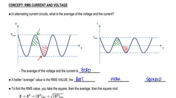
Alternating current (AC) voltage varies sinusoidally over time, and its effective value is often expressed in root mean square (RMS) terms. The RMS value of an AC voltage is equivalent to a direct current (DC) voltage that would deliver the same power to a load. In this question, the source voltage is given as 4.0 V rms, which indicates the effective voltage supplied by the AC source.
추천 영상:
07:14
RMS Current and Voltage

Impedance in AC Circuits

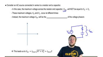
In AC circuits, impedance is the total opposition to current flow, combining resistance and reactance. The impedance of a capacitor varies with frequency, given by the formula Z = 1/(ωC), where ω is the angular frequency and C is the capacitance. The presence of both a resistor and a capacitor in series means that the total voltage across the circuit does not simply equal the sum of the individual voltages due to the phase difference between the current and the voltages across the components.
추천 영상:
08:40
Impedance in AC Circuits

Voltage Division in AC Circuits

Voltage division in AC circuits occurs when the total voltage is distributed across components based on their impedances. The voltage across each component is determined by the ratio of its impedance to the total impedance of the circuit. In this case, the measured voltages across the resistor and capacitor do not add up to the source voltage because of the phase difference and the reactive nature of the capacitor, which affects how voltages are distributed in the circuit.
추천 영상:
08:40
Impedance in AC Circuits
관련 실천
교과서 질문

The frequency of the ac voltage source (peak voltage Vo) in an LRC circuit is tuned to the circuit’s resonant frequency f₀ = 1 / (2π√LC). (a) Show that the peak voltage across the capacitor is Vco = VoTo/ (2πτ), where To ( =1/fo) is the period of the resonant frequency and τ = RC is the time constant for charging the capacitor C through a resistor R. (b) Define β = To/ (2πτ) so that Vco = βVo. Then β is the “amplification” of the source voltage across the capacitor. If a particular LRC circuit contains a 2.0-nF capacitor and has a resonant frequency of 5.0 kHz, what value of R will yield β = 125?

1375
views
교과서 질문

(II) (a) Show that oscillation of charge Q on the capacitor of an LRC circuit has amplitude


Q0=V0(ωR)2+(ω2L1C)2.Q_0 = \(\frac{V_0}{\sqrt{(\omega R)^2 + \left(\omega^2 L - \frac{1}{C}\]\right\))^2}}.

1523
views
교과서 질문

A 10.0-k Ω resistor is in series with a 34.0-mH inductor and an ac source. Calculate the impedance of the circuit if the source frequency is (a) 55.0 Hz; (b) 55.0 kHz.

1179
views
교과서 질문

A 1.50-k Ω resistor in series with a 370-mH inductor is driven by an ac power supply. At what frequency is the impedance double that of the impedance at 60.0 Hz?

1449
views
교과서 질문

An average power output of 150 W is sent into a 4-Ω loudspeaker (see Fig. 25–14). What are the rms voltage and the rms current fed to the speaker at 1.0 W when the volume is turned down?

1468
views
교과서 질문

(II) A capacitor is placed in parallel with some device, B, as in Fig. 30–18b, to filter out stray high-frequency signals, but to allow ordinary 60.0-Hz ac to pass through with little loss. Suppose that circuit B in Fig. 30–18b is a resistance R = 530 Ω connected to ground, and that C = 0.35 μF. Calculate the ratio of the capacitor’s current amplitude to the incoming current’s amplitude if the incoming current has a frequency of (a) 60.0 Hz; (b) 60.0 kHz.

1230
views