
Ch. 30 - Inductance, Electromagnetic Oscillations, and AC Circuits
Giancoli Douglas - Physics for Scientists and Engineers 5th edition
Giancoli Douglas5th editionPhysics for Scientists and EngineersISBN: 9780137488179당신이 사용하는 게 아니라요?교과서 변경
29장, 문제 98

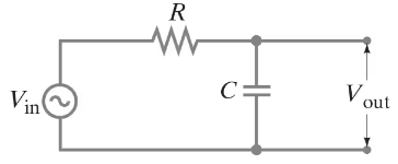
The RC circuit shown in Fig. 30–39 is a low-pass filter because it passes low-frequency ac signals with less attenuation than high-frequency ac signals. (a) Show that the voltage gain is A=Vout/Vin=1/(4π2f2R2C2+1)12A = V_{\(\text{out}\)}/V_{\(\text{in}\)} = 1/(4\(\pi\)^2 f^2 R^2 C^2 + 1)^{\(\frac{1}{2}\)} (b) Discuss the behavior of the gain A for f → 0 and f → ∞.

검증된 단계별 안내
1
Step 1: Start by analyzing the RC circuit. The circuit consists of a resistor (R) and a capacitor (C) in series, with the output voltage (Vₒᵤₜ) taken across the capacitor. The input voltage (Vᵢₙ) is applied across the series combination of R and C.
Step 2: Write the impedance of the resistor and capacitor. The resistor has an impedance Z_R = R, and the capacitor has an impedance Z_C = 1 / (2πfC), where f is the frequency of the input signal.
Step 3: Calculate the total impedance of the series combination. The total impedance Z_total is given by Z_total = Z_R + Z_C = R + 1 / (2πfC).
Step 4: Use the voltage divider rule to find the output voltage Vₒᵤₜ. According to the voltage divider rule, Vₒᵤₜ = Vᵢₙ * (Z_C / Z_total). Substitute Z_C and Z_total into this equation.
Step 5: Simplify the expression for the voltage gain A = Vₒᵤₜ / Vᵢₙ. After simplification, you will find that A = 1 / √(1 + (2πfRC)²). Discuss the behavior of A as f → 0 (low frequency) and f → ∞ (high frequency). For f → 0, A approaches 1, meaning the circuit passes low-frequency signals with minimal attenuation. For f → ∞, A approaches 0, meaning high-frequency signals are heavily attenuated.

비슷한 문제에 대한 검증된 영상 답변:

이 영상 해법은 위 문제에 도움이 된다고 튜터들이 추천한 것입니다.
영상 길이:
8m
도움이 되었나요?

주요 개념

질문에 올바르게 답하기 위해 반드시 이해해야 하는 핵심 개념들은 다음과 같습니다.

RC Circuit

An RC circuit consists of a resistor (R) and a capacitor (C) connected in series or parallel. It is fundamental in filtering applications, where it can either pass or block certain frequencies of an input signal. In a low-pass filter configuration, the circuit allows low-frequency signals to pass while attenuating high-frequency signals, making it essential for applications in audio processing and signal conditioning.
추천 영상:
가이드 코스
03:45
Current in a Parallel RC AC Circuit

Voltage Gain

Voltage gain (A) is a measure of how much an amplifier increases the voltage of a signal. It is defined as the ratio of the output voltage (Vₒᵤₜ) to the input voltage (Vᵢₙ). In the context of the RC low-pass filter, the voltage gain varies with frequency, and understanding its mathematical expression helps analyze how the circuit responds to different input frequencies.
추천 영상:
가이드 코스
07:14
RMS Current and Voltage

Frequency Response

Frequency response describes how the output of a system varies with input frequency. For the RC low-pass filter, as frequency (f) approaches zero, the gain approaches its maximum value, indicating that low frequencies are passed with minimal attenuation. Conversely, as frequency approaches infinity, the gain approaches zero, demonstrating that high frequencies are significantly attenuated, which is crucial for understanding the filter's behavior in practical applications.
추천 영상:
가이드 코스
05:08
Circumference, Period, and Frequency in UCM
관련 실천
교과서 질문

In a plasma globe, a hollow glass sphere is filled with low-pressure gas and a small spherical metal electrode is located at its center. Assume an ac voltage source of peak voltage Vo and frequency f is applied between the metal sphere and the ground, and that a person is touching the outer surface of the globe with a fingertip, whose approximate area is 1.0 cm². The equivalent circuit for this situation is shown in Fig. 30–36, where RG and RP are the resistances of the gas and the person, respectively, and C is the capacitance formed by the gas, glass, and finger. (a) Determine C assuming it is a parallel-plate capacitor. The conductive gas and the person’s fingertip form the opposing plates of area A = 1.0 cm². The plates are separated by glass (dielectric constant K = 5.0) of thickness d = 2.0 mm. (b) In a typical plasma globe, f = 12 kHz. Determine the reactance XC of C at this frequency in MΩ. (c) The voltage may be Vo = 2500 V. With this high voltage, the dielectric strength of the gas is exceeded and the gas becomes ionized. In this “plasma” state, the gas emits light (“sparks”) and is highly conductive so that RG << XC. Assuming also that RP << XC, estimate the peak current that flows in the given circuit. Is this level of current dangerous? (d) If the plasma globe operated at f = 1.0 MHz, estimate the peak current that would flow in the given circuit. Is this level of current dangerous?


<IMAGE>

91
views
교과서 질문

To detect vehicles at traffic lights, wire loops with dimensions on the order of 2 m are often buried horizontally under roadways. Assume the self-inductance of such a coil is L = 5.0 mH and that it is part of an LRC circuit as shown in Fig. 30–40 with C = 0.10 μF and R = 38 Ω. The ac voltage has frequency f and rms voltage Vrms. (a) The frequency f is chosen to match the resonant frequency f₀ of the circuit. Find f₀ and determine what the rms voltage (VR)rms across the resistor will be when f = f₀. (b) Assume that f, C, and R never change, but that, when a car is located above the buried coil, the coil’s self-inductance decreases by 10% (due to induced eddy currents in the car’s metal parts). Determine by what factor the voltage (VR)rms decreases in the presence of a car in comparison to no car above the loop and thus how it detects the presence of a car. (c) Describe how the eddy currents induced in the car reduce L. [Hint: Recall Eq. 30–4, the definition of inductance.]

163
views
교과서 질문

For the circuit shown in Fig. 30–35, show that if the condition R₁ R₂ = L/C is satisfied then the potential difference between points a and b is zero for all frequencies.

1068
views
교과서 질문

Suppose a series LRC circuit has two resistors, R₁ and R₂, two capacitors, C₁ and C₂, and two inductors, L₁ and L₂ all in series. Calculate the total impedance of the circuit.

1507
views