 Indietro
Current, Resistance, and Electromotive Force (EMF): Study Notes
Guida di studio - Note intelligenti
 Appunti personalizzati basati sui tuoi materiali, ampliati con definizioni chiave, esempi e contesto.
Current, Resistance, and Electromotive Force (EMF)
Electric Current
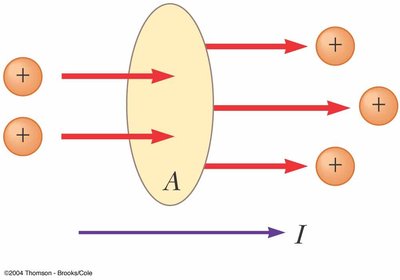
Electric current is the rate at which electric charge flows through a surface or conductor. It is a fundamental concept in understanding how electrical circuits operate.
Definition: Electric current (I) is defined as the amount of charge (Q) passing through a cross-sectional area (A) per unit time (t).
SI Unit: Ampere (A), where 1 A = 1 C/s.
Direction: By convention, current direction is the direction of positive charge flow, even though in metals, electrons (negative charges) are the actual charge carriers.
Formulas:
Average current:
Instantaneous current:
Current and Drift Speed
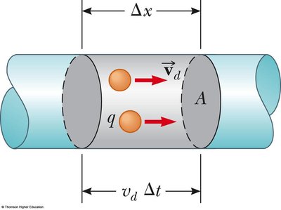
In a conductor, current is carried by charge carriers (typically electrons) moving with an average drift velocity due to an applied electric field.
Drift Velocity (vd): The average velocity at which charge carriers move through a conductor under the influence of an electric field.
Number Density (n): Number of charge carriers per unit volume.
Charge per Carrier (q): For electrons, q = -e.
Current Formula:
Microscopic View of Current
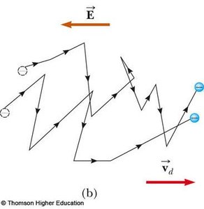
On a microscopic level, electrons move randomly but acquire a net drift velocity in the presence of an electric field, resulting in a current.
Electrons undergo frequent collisions with atoms, causing a zigzag path.
The net motion (drift) is opposite to the electric field for electrons.
Current Density
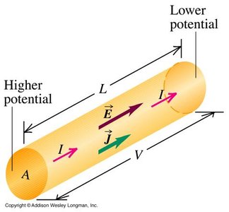
Current density (J) is the current per unit area of cross-section in a conductor.
Formula:
SI Unit: A/m2
Direction: Same as the direction of positive charge flow and the electric field.
Ohm’s Law and Resistance
Ohm’s Law relates the current through a conductor to the voltage across it and its resistance. It is an empirical law valid for many materials (ohmic materials).
Ohm’s Law:
Resistance (R): Opposition to current flow, measured in ohms (Ω).
Resistivity (ρ): A material property, , where L is length and A is cross-sectional area.
Conductivity (σ): Inverse of resistivity, .
Temperature Dependence of Resistance
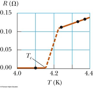
The resistance of most conductors increases with temperature. For some materials, such as semiconductors, resistance decreases with temperature.
Linear Approximation:
Temperature Coefficient (α): Indicates how resistivity changes with temperature.
Superconductors: Materials whose resistance drops to zero below a critical temperature (Tc).
Electromotive Force (EMF) and Internal Resistance
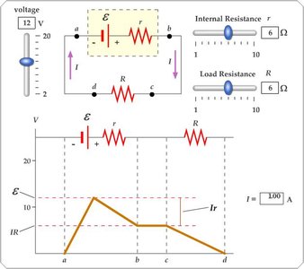
Electromotive force (emf, ε) is the energy provided per unit charge by a source such as a battery. Real sources have internal resistance (r), which reduces the terminal voltage when current flows.
Terminal Voltage:
Current in Circuit:
Open Circuit: Terminal voltage equals emf when I = 0.
Electrical Power in Circuits
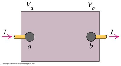
Electrical power is the rate at which energy is delivered to a component in a circuit, such as a resistor.
Power Delivered:
Unit: Watt (W), where 1 W = 1 J/s.
Energy Consumption: Electrical energy is often measured in kilowatt-hours (kWh).
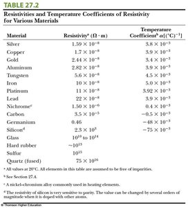
Summary Table: Resistivities and Temperature Coefficients
The following table summarizes the resistivities and temperature coefficients for various materials, which are essential for selecting materials in electrical applications.
Material | Resistivity (Ω·m) | Temperature Coefficient (°C-1) |
|---|---|---|
Silver | 1.59 × 10⁻⁸ | 3.8 × 10⁻³ |
Copper | 1.7 × 10⁻⁸ | 3.9 × 10⁻³ |
Gold | 2.44 × 10⁻⁸ | 3.4 × 10⁻³ |
Aluminum | 2.82 × 10⁻⁸ | 3.9 × 10⁻³ |
Iron | 1.0 × 10⁻⁷ | 6.5 × 10⁻³ |
Lead | 2.2 × 10⁻⁷ | 3.9 × 10⁻³ |
Carbon | 3.5 × 10⁻⁵ | -0.5 × 10⁻³ |
Silicon | 6.4 × 10² | -75 × 10-3 |
Glass | 1010 to 1014 | — |
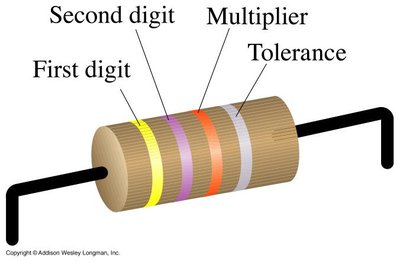
Color Coding for Resistors
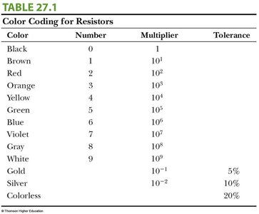
Resistor values are often indicated by colored bands. Each color corresponds to a digit, multiplier, and tolerance.
Color | Number | Multiplier | Tolerance |
|---|---|---|---|
Black | 0 | 1 | |
Brown | 1 | 101 | |
Red | 2 | 102 | |
Orange | 3 | 103 | |
Yellow | 4 | 104 | |
Green | 5 | 105 | |
Blue | 6 | 106 | |
Violet | 7 | 107 | |
Gray | 8 | 108 | |
White | 9 | 109 | |
Gold | 10-1 | 5% | |
Silver | 10-2 | 10% | |
Colorless | 20% |
Ohmic and Nonohmic Materials
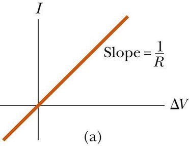
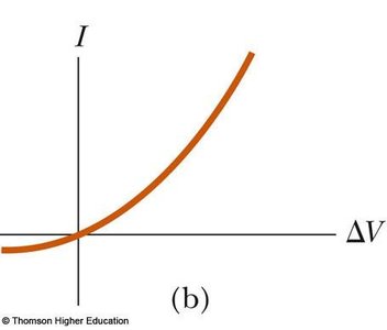
Ohmic materials have a linear relationship between current and voltage, while nonohmic materials do not.
Ohmic: (straight line on I-V graph)
Nonohmic: Nonlinear I-V relationship (e.g., diodes)
Applications: Power Transmission
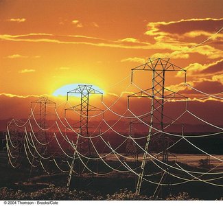
Electric power is transmitted at high voltages and low currents to minimize energy loss due to resistance in transmission lines.
Additional info: These notes provide a comprehensive overview of electric current, resistance, Ohm's law, temperature effects, EMF, and power in circuits, suitable for college-level physics students preparing for exams.
