 Indietro
Kirchhoff’s Laws and RC Circuits: Study Notes for Physics with Calculus
Guida di studio - Note intelligenti
 Appunti personalizzati basati sui tuoi materiali, ampliati con definizioni chiave, esempi e contesto.
Kirchhoff’s Laws in Electrical Circuits
Junction Rule (Kirchhoff’s Current Law)
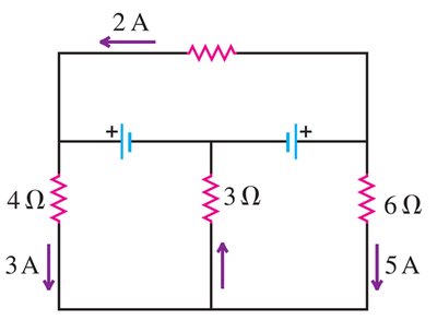
The junction rule states that the sum of currents entering a junction equals the sum of currents leaving the junction. This is a consequence of the conservation of charge.
Definition: At any junction, .
Example: If 3 A and 5 A enter a junction and 8 A leaves, then .
Application: Used to solve for unknown currents in complex circuits.
Loop Rule (Kirchhoff’s Voltage Law)
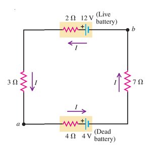
The loop rule states that the sum of the potential differences (voltage) around any closed loop in a circuit is zero. This is based on the conservation of energy.
Definition: For any closed loop, .
Example: In a loop with batteries and resistors, add the EMFs and subtract the IR drops.
Application: Used to solve for unknown voltages or resistances.
Solving Multi-Loop Circuits
Kirchhoff’s laws are essential for analyzing circuits with multiple loops and junctions. By writing equations for each loop and junction, one can solve for unknown currents, voltages, and resistances.
Step 1: Assign current directions and label all circuit elements.
Step 2: Apply the junction rule at each node.
Step 3: Apply the loop rule for each independent loop.
Step 4: Solve the resulting system of equations.
Example Calculation:
Loop 1:
Loop 2:
Loop 3:
Power in Electrical Circuits
Power Supplied and Dissipated
Power in a circuit can be supplied by batteries and dissipated by resistors. The power supplied or absorbed by a battery is given by and the power dissipated by a resistor is .
Live Battery:
Dead Battery:
Resistors: ,
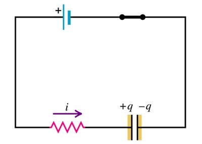
RC Circuits: Charging a Capacitor
Basic RC Circuit Behavior
When a capacitor is charged through a resistor, the current and charge change exponentially with time. The time constant characterizes how quickly the capacitor charges.
Initial Current:
Final Charge:
Time Constant:
Charge at time t:
Current at time t:
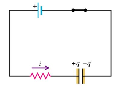
Example: Charge When Current Drops to 1/5 Initial Value
To find the charge when the current is 1/5 of its initial value, use the exponential decay formula for current and solve for time, then substitute into the charge formula.
Energy Stored in a Capacitor
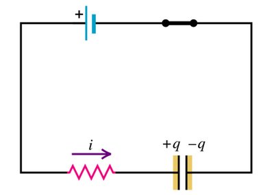
The energy stored in a capacitor is given by . At any time, the energy is .
Maximum Energy:
Energy at half maximum: Find such that
Summary Table: Key Formulas for Kirchhoff’s Laws and RC Circuits
Concept | Formula | Description |
|---|---|---|
Junction Rule | Conservation of charge at a junction | |
Loop Rule | Conservation of energy in a loop | |
Resistor Power | Power dissipated by a resistor | |
Battery Power | Power supplied or absorbed by a battery | |
RC Time Constant | Characteristic time for charging/discharging | |
Capacitor Charge | Charge on capacitor at time t | |
Capacitor Current | Current in circuit at time t | |
Capacitor Energy | Energy stored in capacitor |
