 Indietro
Thin Lenses and Spherical Mirrors: Ray Tracing and Image Formation
Guida di studio - Note intelligenti
 Appunti personalizzati basati sui tuoi materiali, ampliati con definizioni chiave, esempi e contesto.
Thin Lenses: Ray Tracing
Introduction to Thin Lenses
Thin lenses are transparent optical devices that use refraction at curved surfaces to form images. Ray tracing is a graphical method used to analyze and predict the formation and properties of images produced by lenses.
Converging lenses are thicker at the center than at the edges and refract parallel rays toward the optical axis.
Diverging lenses are thinner at the center than at the edges and refract parallel rays away from the optical axis.
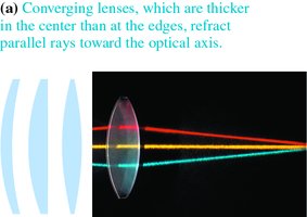
Refraction at Lens Surfaces
When light passes through a lens, it bends (refracts) at both the air-to-glass and glass-to-air boundaries. In a converging lens, rays bend toward the optical axis at both surfaces, focusing the rays.
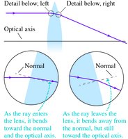
Focal Points and Focal Length
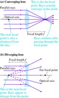
Parallel rays entering a lens converge (or appear to diverge) at a specific point called the focal point. The distance from the lens to the focal point is the focal length (f), determined by the lens curvature and refractive index.
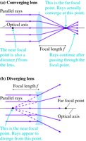
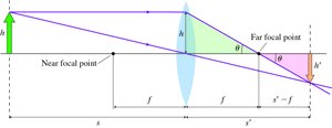
There are focal points on both sides of a lens: the near focal point (same side as incoming light) and the far focal point (opposite side).
Ray Tracing Rules for Converging Lenses
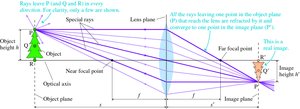
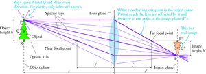
Ray tracing for thin lenses uses three principal rays to locate the image:
A ray parallel to the optical axis refracts through the far focal point.
A ray passing through the near focal point emerges parallel to the optical axis.
A ray directed at the center of the lens passes straight through without bending.
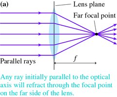
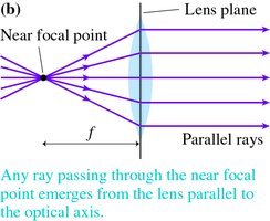
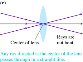
Image Formation by Lenses
Real Images
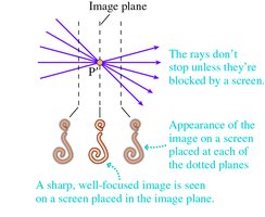
A real image is formed when refracted rays converge at a point on the far side of the lens. Real images are inverted relative to the object and can be projected onto a screen.

Magnification
The magnification (m) of a lens describes the ratio of image height to object height and the orientation of the image:
, where is image height and is object height.
A positive means the image is upright; a negative means the image is inverted.
Virtual Images
A virtual image is formed when the refracted rays diverge and appear to originate from a point on the same side of the lens as the object. Virtual images are upright and cannot be projected onto a screen, but can be seen by looking through the lens (e.g., a magnifying glass).
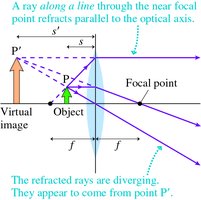
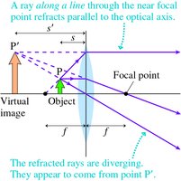
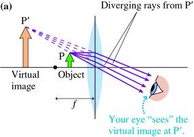
For virtual images, the image distance is negative by convention.
Diverging Lenses
Ray Tracing for Diverging Lenses
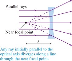
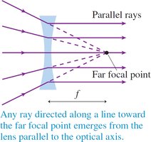
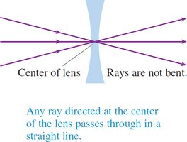
Diverging lenses always produce virtual, upright, and reduced images. The ray tracing rules are:
A ray parallel to the optical axis diverges as if from the near focal point.
A ray directed toward the far focal point emerges parallel to the optical axis.
A ray through the center of the lens passes straight through.
Spherical Mirrors: Ray Tracing and Image Formation
Types of Spherical Mirrors
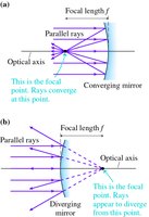
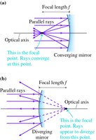
Spherical mirrors are curved mirrors that can be either converging (concave) or diverging (convex):
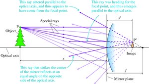
Converging (concave) mirrors reflect parallel rays through a focal point in front of the mirror.
Diverging (convex) mirrors reflect parallel rays as if they originated from a focal point behind the mirror.
Ray Tracing for Converging Mirrors
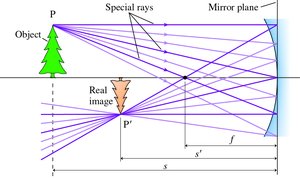
Three principal rays are used for ray tracing with mirrors:
A ray parallel to the optical axis reflects through the focal point.
A ray passing through the focal point reflects parallel to the optical axis.
A ray directed at the center of the mirror reflects at an equal angle on the opposite side of the axis.
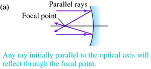
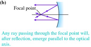
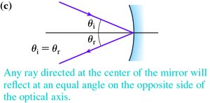
Image Formation by Mirrors
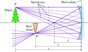
Converging mirrors can form real or virtual images depending on the object's position relative to the focal length. Real images are inverted and can be projected; virtual images are upright and cannot be projected.
Ray Tracing for Diverging Mirrors
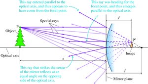
Diverging (convex) mirrors always produce virtual, upright, and reduced images. The principal rays are similar to those for lenses but follow the law of reflection.

The Thin-Lens Equation
Mathematical Relationship
The thin-lens equation relates the object distance (s), image distance (s'), and focal length (f) of a lens or mirror:
For lenses and mirrors:
Magnification:
Sign Conventions
For converging lenses/mirrors, f is positive; for diverging, f is negative.
Real images (inverted): s' is positive.
Virtual images (upright): s' is negative.
Summary Table: Image Types and Sign Conventions
Situation | Image Type | Orientation | Sign of s' | Sign of f |
|---|---|---|---|---|
Converging lens/mirror, object outside f | Real | Inverted | + | + |
Converging lens/mirror, object inside f | Virtual | Upright | - | + |
Diverging lens/mirror | Virtual | Upright | - | - |
Key Concepts and Applications
Ray diagrams are essential for visualizing image formation and predicting image properties.
Magnification and the thin-lens equation allow quantitative analysis of image size and location.
Sign conventions must be carefully applied for correct interpretation of results.
