Ch. 26 - DC Circuits
Giancoli Douglas - Physics for Scientists and Engineers 5th edition
Giancoli Douglas5th editionPhysics for Scientists and EngineersISBN: 9780137488179Non è quello che usi tu?Cambia libro di testo
Capitolo 25, Problema 58b

A galvanometer has an internal resistance of 32 Ω and deflects full scale for a 48-μA current. Describe how to use this galvanometer to make a voltmeter to give a full scale deflection of 250 V.

Guida verificata passo dopo passo
1
Determine the total resistance required for the voltmeter to give a full-scale deflection at 250 V. Using Ohm's Law, the total resistance R_total is given by: Rtotal=VI, where V = 250 V and I = 48 μA.
Calculate the resistance that needs to be added in series with the galvanometer. The total resistance of the voltmeter is the sum of the internal resistance of the galvanometer (R_g = 32 Ω) and the series resistance (R_s). Therefore, Rs=Rtotal-Rg.
Substitute the values of R_total and R_g into the equation to find R_s. This will give the resistance that must be added in series with the galvanometer to create the desired voltmeter.
Connect the calculated series resistance (R_s) in series with the galvanometer. This configuration ensures that the galvanometer will deflect full scale when the voltage across the entire circuit is 250 V.
Verify the setup by checking that the total resistance of the voltmeter matches the calculated R_total and that the galvanometer deflects full scale at 250 V.

Risposta video verificata per un problema simile:

Questa soluzione video è stata consigliata dai nostri tutor come utile per risolvere questo problema.
Durata del video:
3m

Concetti chiave

Ecco i concetti essenziali che devi comprendere per rispondere correttamente alla domanda.

Galvanometer

A galvanometer is an electromechanical device used to detect and measure small electric currents. It operates by using a coil of wire that experiences a magnetic field, causing it to rotate and indicate the current level on a scale. The full-scale deflection indicates the maximum current the galvanometer can measure, which is crucial for converting it into other measuring instruments.

Internal Resistance

Internal resistance refers to the resistance within a device, such as a galvanometer, that opposes the flow of current. In this context, the internal resistance of 32 Ω affects how the galvanometer interacts with external circuits. Understanding this resistance is essential for calculating how to connect the galvanometer to measure higher voltages without damaging it.
Video consigliato:
Percorso guidato
04:54
Total Internal Energy

Voltage Divider

A voltage divider is a simple circuit that uses resistors to produce a lower voltage from a higher voltage source. By adding a series resistor to the galvanometer, the voltage across the galvanometer can be controlled, allowing it to measure higher voltages without exceeding its full-scale deflection. This principle is key to converting the galvanometer into a voltmeter capable of measuring up to 250 V.
Video consigliato:
Percorso guidato
07:14
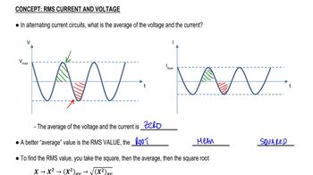
RMS Current and Voltage
Pratica correlata
Domanda del libro di testo

A galvanometer has a sensitivity of 45kΩ/V and internal resistance 20.0 Ω. How could you make this into an ammeter that reads 1.0 A full scale?

810
views

Domanda del libro di testo

(II) Suppose two batteries, with unequal emfs of 2.00 V and 3.00 V, are connected as shown in Fig. 26–63. If each internal resistance is r = 0.350Ω and R = 4.00Ω, what is the voltage across the resistor R?

803
views
Domanda del libro di testo

In the circuit shown in Fig. 26–75, the 33-Ω resistor dissipates 0.80 W. What is the battery voltage?

1309
views
Domanda del libro di testo

A galvanometer has an internal resistance of 32 Ω and deflects full scale for a 48-μA current. Describe how to use this galvanometer to make an ammeter to read currents up to 25 A.

1288
views
Domanda del libro di testo

The circuit shown in Fig. 26–89 is a primitive 4-bit digital-to-analog converter (DAC). In this circuit, to represent each digit (2n) of a binary number, a “1” has the nᵗʰ switch closed whereas zero (“0”) has the switch open. For example, 0010 is represented by closing switch n = 1, while all other switches are open. Show that the voltage V across the 1.0 - Ω resistor for the binary numbers 0001, 0010, 0100, and 1010 (which represent 1, 2, 4, 10) follows the pattern that you expect for a 4-bit DAC.


778
views
Domanda del libro di testo

The performance of the starter circuit in a car can be significantly degraded by a small amount of corrosion on a battery terminal. Figure 26–88a depicts a properly functioning circuit with a battery (12.5-V emf, 0.02-Ω internal resistance) attached via corrosion-free cables to a starter motor of resistance Rs = 0.15Ω. Sometime later, corrosion between a battery terminal and a starter cable introduces an extra series resistance of only RC = 0.10Ω into the circuit as suggested in Fig. 26–88b. Let P0 be the power delivered to the starter in the circuit free of corrosion, and let P be the power delivered to the starter with corrosion. Determine the ratio P/P0.

955
views