
Ch 26: Potential and Field
Knight Calc - Physics for Scientists and Engineers 5th Edition
Knight Calc5th EditionPhysics for Scientists and EngineersISBN: 9780137344796Non è quello che usi tu?Cambia libro di testo
Capitolo 26, Problema 57

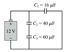
What are the charge on and the potential difference across each capacitor in FIGURE P26.57?
Circuit diagram showing a 12V battery connected to three capacitors: C1 (16μF), C2 (40μF), and C3 (60μF).

Guida verificata passo dopo passo
1
Step 1: Analyze the circuit configuration. Capacitor C1 is in series with the combination of capacitors C2 and C3, which are connected in parallel. This means the equivalent capacitance of C2 and C3 must be calculated first.
Step 2: Calculate the equivalent capacitance of C2 and C3 using the formula for capacitors in parallel: Ceq=C2+C3. Substitute the values: Ceq=40+60=100μF.
Step 3: Calculate the total equivalent capacitance of the circuit. Since C1 is in series with the equivalent capacitance of C2 and C3, use the formula for capacitors in series: 1Ctotal=1C1+1Ceq. Substitute the values: 1Ctotal=116+1100.
Step 4: Determine the charge on C1 using the formula Q=Ctotal×V, where V is the voltage of the battery (12 V). Once the charge on C1 is known, the same charge will be present on the equivalent capacitance of C2 and C3 because capacitors in series share the same charge.
Step 5: Calculate the potential difference across each capacitor. For C1, use V1=QC1. For C2 and C3, first calculate the voltage across the equivalent capacitance using Veq=QCeq, then split the voltage across C2 and C3 proportionally based on their capacitances.

Risposta video verificata per un problema simile:

Questa soluzione video è stata consigliata dai nostri tutor come utile per risolvere questo problema.

Concetti chiave

Ecco i concetti essenziali che devi comprendere per rispondere correttamente alla domanda.

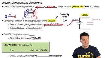
Capacitance

Capacitance is the ability of a capacitor to store charge per unit voltage, measured in farads (F). In this circuit, capacitors C1, C2, and C3 have capacitances of 16μF, 40μF, and 60μF, respectively. The total capacitance in a circuit depends on whether the capacitors are arranged in series or parallel, affecting how they share voltage and charge.
Video consigliato:
Percorso guidato
08:02
Capacitors & Capacitance (Intro)

Voltage in Capacitors

The voltage across a capacitor is directly related to the charge stored and its capacitance, described by the formula V = Q/C, where V is voltage, Q is charge, and C is capacitance. In this circuit, the potential difference across each capacitor must be calculated based on their arrangement and the total voltage supplied by the battery, which is 12V.
Video consigliato:
Percorso guidato
07:14
RMS Current and Voltage

Series and Parallel Capacitor Configurations

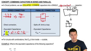
Capacitors can be connected in series or parallel, affecting their overall behavior. In series, the total capacitance decreases, and the same charge flows through each capacitor, while the voltage divides among them. In parallel, the total capacitance increases, and each capacitor experiences the same voltage. Understanding this configuration is crucial for determining the charge and voltage across each capacitor in the given circuit.
Video consigliato:
Percorso guidato
09:51
Combining Capacitors in Series & Parallel
Pratica correlata