Ch 28: Fundamentals of Circuits
Knight Calc - Physics for Scientists and Engineers 5th Edition
Knight Calc5th EditionPhysics for Scientists and EngineersISBN: 9780137344796Non è quello che usi tu?Cambia libro di testo
Capitolo 28, Problema 61

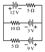
What is the current through the 10 Ω resistor in FIGURE P28.61? Is the current from left to right or right to left?
Circuit diagram showing a 12V battery, resistors of 5Ω, 10Ω, and 5Ω, and voltage sources of 3V and 9V.

Guida verificata passo dopo passo
1
Step 1: Analyze the circuit diagram. The circuit consists of three branches, each containing a resistor and a voltage source. The 10 Ω resistor is in the middle branch, and we need to determine the current through it and its direction.
Step 2: Apply Kirchhoff's Voltage Law (KVL) to each loop in the circuit. KVL states that the sum of the voltage drops and rises around any closed loop is zero. Write equations for the top loop, middle loop, and bottom loop.
Step 3: Use Ohm's Law, which states that V = I × R, to express the voltage drops across each resistor in terms of the current through them. For example, the voltage drop across the 10 Ω resistor is 10 × I_10, where I_10 is the current through the 10 Ω resistor.
Step 4: Solve the system of equations obtained from KVL to find the currents in each branch. Pay attention to the direction of the currents based on the polarity of the voltage sources.
Step 5: Determine the direction of the current through the 10 Ω resistor. If the current flows from the positive terminal of the 3 V battery to the negative terminal, it is from left to right. Otherwise, it is from right to left.

Risposta video verificata per un problema simile:

Questa soluzione video è stata consigliata dai nostri tutor come utile per risolvere questo problema.

Concetti chiave

Ecco i concetti essenziali che devi comprendere per rispondere correttamente alla domanda.

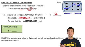
Ohm's Law

Ohm's Law states that the current (I) flowing through a conductor between two points is directly proportional to the voltage (V) across the two points and inversely proportional to the resistance (R) of the conductor. This relationship is expressed mathematically as I = V/R. Understanding this law is essential for calculating the current through resistors in a circuit.
Video consigliato:
Percorso guidato
03:07
Resistance and Ohm's Law

Series and Parallel Circuits

In electrical circuits, components can be arranged in series or parallel. In a series circuit, the current is the same through all components, while the total voltage is the sum of the individual voltages. In a parallel circuit, the voltage across each component is the same, and the total current is the sum of the currents through each path. Recognizing the configuration of the resistors is crucial for analyzing the circuit.
Video consigliato:
Percorso guidato
09:51
Combining Capacitors in Series & Parallel

Kirchhoff's Voltage Law

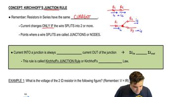
Kirchhoff's Voltage Law states that the sum of the electrical potential differences (voltage) around any closed network is zero. This means that the total voltage supplied by sources in a circuit must equal the total voltage drop across the resistors. Applying this law helps in determining the voltage across each resistor and, consequently, the current flowing through them.
Video consigliato:
Percorso guidato
04:08
Kirchhoff's Junction Rule
Pratica correlata
Domanda del libro di testo

What are the battery current Ibat and the potential difference V₁ - V₂ between points 1 and 2 when the switch in FIGURE P28.55 is (a) open and (b) closed?

170
views

Domanda del libro di testo

A 12 V car battery dies not so much because its voltage drops but because chemical reactions increase its internal resistance. A good battery connected with jumper cables can both start the engine and recharge the dead battery. Consider the automotive circuit of FIGURE P28.64. How much current is the dead battery alone able to drive through the starter motor?

1729
views
Domanda del libro di testo

The capacitor in an RC circuit is discharged with a time constant of 10 ms. At what time after the discharge begins are (a) the charge on the capacitor reduced to half its initial value and (b) the energy stored in the capacitor reduced to half its initial value?

150
views
Domanda del libro di testo

Load resistor R is attached to a battery of emf and internal resistance r. For what value of the resistance R, in terms of ∈ and r, will the power dissipated by the load resistor be a maximum?

572
views
Domanda del libro di testo

How much current flows through the bottom wire in FIGURE P28.66, and in which direction?

204
views
Domanda del libro di testo

A circuit you're building needs an ammeter that goes from 0 mA to a full-scale reading of 50 mA. Unfortunately, the only ammeter in the storeroom goes from 0 μA to a full-scale reading of only 500 μA. Fortunately, you've just finished a physics class, and you realize that you can make this ammeter work by putting a resistor in parallel with it, as shown in FIGURE P28.56. You've measured that the resistance of the ammeter is 50.0 Ω, not the 0 Ω of an ideal ammeter. What is the effective resistance of your ammeter?

63
views