A series RLC circuit with ε0 = 10.0 V consists of a 1.0 Ω resistor, a 1.0 μH inductor, and a 1.0 μF capacitor. What is V1 at ω = ω0 and at ω = ω1?
Ch 32: AC Circuits
Knight Calc5th EditionPhysics for Scientists and EngineersISBN: 9780137344796Non è quello che usi tu?Cambia libro di testo
Capitolo 32, Problema 68a
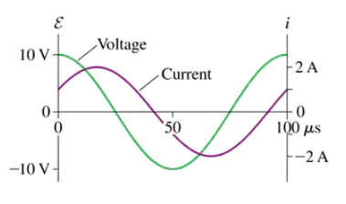
FIGURE CP32.68 shows voltage and current graphs for a series RLC circuit. What is the resistance R?

Guida verificata passo dopo passo1
Step 1: Observe the voltage and current graphs provided in the figure. The voltage graph (purple) and current graph (green) are sinusoidal and appear to be in phase, which indicates that the circuit is purely resistive.
Step 2: Recall Ohm's Law for a resistive circuit, which states that the resistance R can be calculated using the formula: , where V is the peak voltage and I is the peak current.
Step 3: From the voltage graph, identify the peak voltage. The graph shows that the maximum voltage is 10 V.
Step 4: From the current graph, identify the peak current. The graph shows that the maximum current is 2 A.
Step 5: Substitute the peak voltage and peak current values into the formula for resistance: . Simplify the expression to find the resistance.
Concetti chiave
Ecco i concetti essenziali che devi comprendere per rispondere correttamente alla domanda.
RLC Circuit
An RLC circuit is an electrical circuit consisting of a resistor (R), inductor (L), and capacitor (C) connected in series or parallel. The behavior of the circuit is characterized by its impedance, which combines the effects of resistance, inductance, and capacitance. Understanding the RLC circuit is crucial for analyzing how voltage and current interact over time, especially in alternating current (AC) systems.
Video consigliato:
Percorso guidato
LRC Circuits
Phase Difference
In AC circuits, voltage and current can oscillate out of phase, meaning they reach their maximum and minimum values at different times. The phase difference is measured in degrees or radians and affects the power factor of the circuit. In the context of the given graphs, analyzing the phase difference between the voltage and current waveforms is essential for determining the resistance and overall behavior of the RLC circuit.
Video consigliato:
Percorso guidato
Phase Constant of a Wave Function
Ohm's Law
Ohm's Law states that the current (I) flowing through a conductor between two points is directly proportional to the voltage (V) across the two points and inversely proportional to the resistance (R) of the conductor. This fundamental principle is expressed as V = IR. In the context of the RLC circuit, applying Ohm's Law helps in calculating the resistance by analyzing the relationship between the voltage and current waveforms shown in the graphs.
Video consigliato:
Percorso guidato
Resistance and Ohm's Law
Pratica correlata
Domanda del libro di testo
295
views
Domanda del libro di testo
Prove that the energy dissipation is a maximum at ω = ω₀.
124
views
Domanda del libro di testo
A motor attached to a 120 V/60 Hz power line draws an 8.0 A current. Its average energy dissipation is 800 W. What is the motor's resistance?
204
views
Domanda del libro di testo
A motor attached to a 120 V/60 Hz power line draws an 8.0 A current. Its average energy dissipation is 800 W. What is the rms resistor voltage?
158
views
Domanda del libro di testo
A motor attached to a 120 V/60 Hz power line draws an 8.0 A current. Its average energy dissipation is 800 W. How much series capacitance needs to be added to increase the power factor to 1.0?
1723
views
Domanda del libro di testo
Show that the peak inductor voltage in a series RLC circuit is maximum at frequency .
188
views