
Ch 32: AC Circuits
Knight Calc - Physics for Scientists and Engineers 5th Edition
Knight Calc5th EditionPhysics for Scientists and EngineersISBN: 9780137344796Non è quello che usi tu?Cambia libro di testo
Capitolo 32, Problema 49a

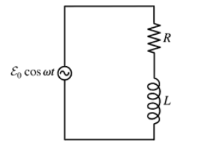
Use a phasor diagram to analyze the RL circuit of FIGURE P32.49. In particular, Find expressions for I, VR, and VL.

Guida verificata passo dopo passo
1
Step 1: Understand the components of the RL circuit. An RL circuit consists of a resistor (R) and an inductor (L) connected in series with an alternating current (AC) source. The current (I) is the same through both components, but the voltage across the resistor (V_R) and the inductor (V_L) will differ in phase due to the inductive reactance.
Step 2: Represent the voltages and current as phasors. In an RL circuit, the voltage across the resistor (V_R) is in phase with the current (I), while the voltage across the inductor (V_L) leads the current by 90 degrees. Use a phasor diagram to represent these relationships, with the current phasor as the reference (horizontal axis).
Step 3: Write the expressions for the voltages. The voltage across the resistor is given by \( V_R = I R \), where \( R \) is the resistance. The voltage across the inductor is given by \( V_L = I X_L \), where \( X_L = \omega L \) is the inductive reactance, and \( \omega \) is the angular frequency of the AC source.
Step 4: Use the phasor diagram to find the total voltage. The total voltage \( V \) is the vector sum of \( V_R \) and \( V_L \). Since \( V_R \) and \( V_L \) are perpendicular, the magnitude of the total voltage is \( V = \sqrt{V_R^2 + V_L^2} \). Substitute the expressions for \( V_R \) and \( V_L \) to get \( V = \sqrt{(I R)^2 + (I X_L)^2} \).
Step 5: Solve for the current \( I \). The current can be expressed as \( I = \frac{V}{\sqrt{R^2 + X_L^2}} \). Once \( I \) is known, substitute it back into the expressions for \( V_R \) and \( V_L \) to find their respective values. This completes the analysis of the RL circuit using a phasor diagram.

Risposta video verificata per un problema simile:

Questa soluzione video è stata consigliata dai nostri tutor come utile per risolvere questo problema.

Concetti chiave

Ecco i concetti essenziali che devi comprendere per rispondere correttamente alla domanda.

Phasor Diagrams

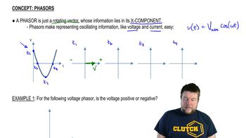
Phasor diagrams are graphical representations of sinusoidal functions, where each phasor represents the amplitude and phase of a sinusoidal voltage or current. In the context of AC circuits, phasors simplify the analysis of circuit elements by converting time-dependent sinusoidal signals into complex numbers, allowing for easier calculations of voltages and currents in the circuit.
Video consigliato:

RL Circuit

An RL circuit consists of a resistor (R) and an inductor (L) connected in series or parallel. The behavior of an RL circuit is characterized by its impedance, which combines resistance and inductive reactance. The inductor introduces a phase shift between the voltage and current, affecting the overall circuit response to alternating current (AC) signals, which is crucial for determining the expressions for current and voltages across the components.
Video consigliato:

Impedance

Impedance is a measure of how much a circuit resists the flow of alternating current, combining both resistance (R) and reactance (X). In an RL circuit, the impedance is given by Z = R + jωL, where j is the imaginary unit and ω is the angular frequency of the AC source. Understanding impedance is essential for calculating the current (I) and the voltages across the resistor (VR) and inductor (VL) using Ohm's law and Kirchhoff's laws in the phasor domain.
Video consigliato:
Percorso guidato
08:40
Impedance in AC Circuits
Pratica correlata
Domanda del libro di testo

You have a resistor and a capacitor of unknown values. First, you charge the capacitor and discharge it through the resistor. By monitoring the capacitor voltage on an oscilloscope, you see that the voltage decays to half its initial value in 2.5 ms. You then use the resistor and capacitor to make a low-pass filter. What is the crossover frequency fc?

65
views
Domanda del libro di testo

Use a phasor diagram to analyze the RL circuit of FIGURE P32.49. In particular, What is VR in the limits ω→0 and ω→∞?

97
views
Domanda del libro di testo

The small transformers that power many consumer products produce a 12.0 V rms, 60 Hz emf. Design a circuit using resistors and capacitors that uses the transformer voltage as an input and produces a 6.0 V rms output that leads the input voltage by 45°.

1195
views
Domanda del libro di testo

Use a phasor diagram to analyze the RL circuit of FIGURE P32.49. In particular, Find an expression for the crossover frequency ωc.

122
views
Domanda del libro di testo

A series RC circuit is built with a 12 kΩ resistor and a parallel-plate capacitor with 15-cm-diameter electrodes. A 12 V, 36 kHz source drives a peak current of 0.65 mA through the circuit. What is the spacing between the capacitor plates?

60
views
1
rank
Domanda del libro di testo

A series RL circuit is built with a 110 Ω resistor and a 5.0-cm-long, 1.0-cm-diameter solenoid with 800 turns of wire. What is the peak magnetic flux through the solenoid if the circuit is driven by a 12 V, 5.0 kHz source?

79
views