Ch 31: Alternating Current
Young & Freedman Calc - University Physics 14th Edition
Young & Freedman Calc14th EditionUniversity PhysicsISBN: 9780321973610Non è quello che usi tu?Cambia libro di testo
Capitolo 31, Problema 20

In an L-R-C series circuit, the components have the following values: L = 20.0 mH, C = 140 nF, and R = 350 Ω.The generator has an rms voltage of 120 V and a frequency of 1.25 kHz. Determine (a) the power supplied by the generator and (b) the power dissipated in the resistor.

Guida verificata passo dopo passo
1
First, calculate the angular frequency (ω) of the circuit using the formula ω = 2πf, where f is the frequency of the generator. Substitute f = 1.25 kHz into the formula to find ω.
Next, determine the inductive reactance (X_L) using the formula X_L = ωL, where L is the inductance. Substitute the values of ω and L = 20.0 mH to find X_L.
Calculate the capacitive reactance (X_C) using the formula X_C = 1/(ωC), where C is the capacitance. Substitute the values of ω and C = 140 nF to find X_C.
Find the total impedance (Z) of the circuit using the formula Z = √(R² + (X_L - X_C)²). Substitute the values of R, X_L, and X_C to find Z.
Finally, calculate the power supplied by the generator using the formula P = (V_rms²)/Z, where V_rms is the rms voltage of the generator. Then, calculate the power dissipated in the resistor using the formula P_R = (V_rms²)/R.

Risposta video verificata per un problema simile:

Questa soluzione video è stata consigliata dai nostri tutor come utile per risolvere questo problema.
Durata del video:
10m

Concetti chiave

Ecco i concetti essenziali che devi comprendere per rispondere correttamente alla domanda.

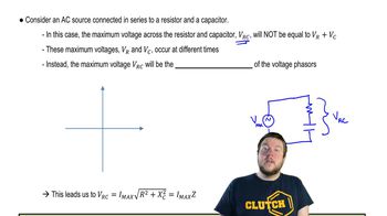
Impedance in L-R-C Circuits

Impedance is the total opposition a circuit offers to the flow of alternating current, combining resistance (R), inductive reactance (XL), and capacitive reactance (XC). In an L-R-C series circuit, impedance (Z) is calculated using Z = √(R² + (XL - XC)²), where XL = 2πfL and XC = 1/(2πfC). Understanding impedance is crucial for determining the current and power in the circuit.
Video consigliato:
Percorso guidato
08:40
Impedance in AC Circuits

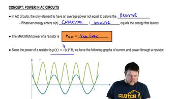
Power in AC Circuits

In AC circuits, power is calculated using the formula P = Vrms * Irms * cos(φ), where φ is the phase angle between voltage and current. The real power dissipated in the resistor is given by P = I²R, where I is the current through the resistor. This concept helps in calculating both the power supplied by the generator and the power dissipated in the resistor.
Video consigliato:
Percorso guidato
05:37
Power in AC Circuits

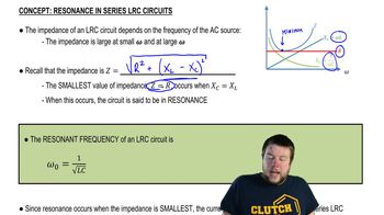
Resonance in L-R-C Circuits

Resonance occurs in an L-R-C circuit when the inductive reactance equals the capacitive reactance (XL = XC), resulting in maximum current flow. At resonance, the impedance is minimized, and the circuit behaves purely resistive. Understanding resonance is essential for analyzing the circuit's behavior at different frequencies, especially when calculating power.
Video consigliato:
Percorso guidato
05:23
Resonance in Series LRC Circuits
Pratica correlata