
Ch 26: Direct-Current Circuits
Young & Freedman Calc - University Physics 14th Edition
Young & Freedman Calc14th EditionUniversity PhysicsISBN: 9780321973610Non è quello che usi tu?Cambia libro di testo
Capitolo 26, Problema 31b

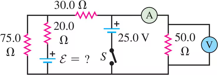
In the circuit shown in Fig. E26.31 the batteries have negligible internal resistance and the meters are both idealized. With the switch S open, the voltmeter reads 15.0 V. What will the ammeter read when the switch is closed?

Guida verificata passo dopo passo
1
Identify the components in the circuit: There are two batteries, one with an unknown emf (E) and another with 52.0 V. The resistors are 10.0 Ω, 18.0 Ω, 40.0 Ω, 14.0 Ω, and 25.0 Ω. The voltmeter reads 15.0 V when the switch is open.
Calculate the total resistance in the circuit when the switch is closed. The 18.0 Ω and 40.0 Ω resistors are in series, and their equivalent resistance is R1 = 18.0 Ω + 40.0 Ω. The 14.0 Ω and 25.0 Ω resistors are also in series, with an equivalent resistance of R2 = 14.0 Ω + 25.0 Ω.
Determine the total resistance in the circuit. The resistors R1 and R2 are in parallel, so their combined resistance is given by 1/R_parallel = 1/R1 + 1/R2. Add the 10.0 Ω resistor in series to find the total resistance R_total = 10.0 Ω + R_parallel.
Use Kirchhoff's loop rule to find the current through the circuit. The loop rule states that the sum of the emfs in any closed loop is equal to the sum of the potential drops (IR) across the resistors. Set up the equation: E - I * R_total = 0, where E is the total emf (52.0 V + E).
Solve for the current I using the equation from the previous step. The current I is what the ammeter will read when the switch is closed. Rearrange the equation to find I = E / R_total.

Risposta video verificata per un problema simile:

Questa soluzione video è stata consigliata dai nostri tutor come utile per risolvere questo problema.
Durata del video:
9m

Concetti chiave

Ecco i concetti essenziali che devi comprendere per rispondere correttamente alla domanda.

Ohm's Law

Ohm's Law is a fundamental principle in electronics and electrical engineering, stating that the current (I) through a conductor between two points is directly proportional to the voltage (V) across the two points and inversely proportional to the resistance (R) of the conductor. It is mathematically expressed as V = IR. This law is crucial for calculating the current in the circuit when the switch is closed.
Video consigliato:
Percorso guidato
03:07
Resistance and Ohm's Law

Series and Parallel Circuits

In a series circuit, components are connected end-to-end, so the same current flows through each component. In a parallel circuit, components are connected across the same voltage source, so the voltage across each component is the same. Understanding these configurations is essential for analyzing the circuit's total resistance and the current distribution when the switch is closed.
Video consigliato:
Percorso guidato
09:51
Combining Capacitors in Series & Parallel

Kirchhoff's Voltage Law

Kirchhoff's Voltage Law (KVL) states that the sum of the electrical potential differences (voltage) around any closed network is zero. This principle helps in analyzing the circuit by ensuring that the total voltage supplied by the batteries equals the sum of the voltage drops across the resistors, which is necessary to determine the current through the ammeter when the switch is closed.
Video consigliato:
Percorso guidato
04:08
Kirchhoff's Junction Rule
Pratica correlata
Domanda del libro di testo

The 10.00 V battery in Fig. E26.28 is removed from the circuit and reinserted with the opposite polarity, so that its positive terminal is now next to point a. The rest of the circuit is as shown in the figure. Find the current in each branch.

1386
views
Domanda del libro di testo

In the circuit shown in Fig. E26.34, the 6.0 Ω resistor is consuming energy at a rate of 24 J/s when the current through it flows as shown. What are the polarity and emf ε of the unknown battery, assuming it has negligible internal resistance?

2733
views
2
rank
1
comments
Domanda del libro di testo

The 5.00 V battery in Fig. E26.28 is removed from the circuit and replaced by a 15.00 V battery, with its negative terminal next to point b. The rest of the circuit is as shown in the figure. Find the current in each branch.

3120
views
1
comments
Domanda del libro di testo

An emf source with ε = 120V, a resistor with R = 80.0Ω, and a capacitor with C = 4.00 μF are connected in series. As the capacitor charges, when the current in the resistor is 0.900 A, what is the magnitude of the charge on each plate of the capacitor?

1506
views
Domanda del libro di testo

In the circuit shown in Fig. E26.27 find the unknown emfs ε1ε_1 and ε2ε_2.

1472
views
Domanda del libro di testo

In the circuit shown in Fig. E26.33 all meters are idealized and the batteries have no appreciable internal resistance. Find the reading of the voltmeter with the switch S open. Which point is at a higher potential: a or b?

1915
views