 뒤로
뒤로DC Circuits: Series, Parallel, and RC Circuits
스터디 가이드 - 스마트 노트
 자료에 맞춘 맞춤형 노트, 핵심 정의, 예시, 맥락을 확장해 제공합니다.
DC Circuits
EMF and Terminal Voltage
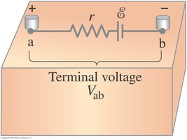
In a direct current (DC) circuit, the electromotive force (EMF) of a battery provides the energy to drive current through the circuit. The terminal voltage is the voltage measured across the terminals of the battery, which can differ from the EMF due to internal resistance.
EMF (\( \mathcal{E} \)): The maximum potential difference a battery can provide when no current is flowing.
Internal Resistance (\( r \)): The resistance inside the battery, which causes the terminal voltage to drop when current flows.
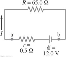
Terminal Voltage (\( V_{ab} \)): Given by \( V_{ab} = \mathcal{E} - Ir \), where \( I \) is the current.
Example: If a battery has \( \mathcal{E} = 12 \) V and \( r = 0.5 \Omega \), and the current is \( 1 \) A, then \( V_{ab} = 12 - (1 \times 0.5) = 11.5 \) V.
Resistors in Series and Parallel
Resistors can be connected in series or parallel, affecting the total resistance and current distribution in the circuit. Understanding these configurations is essential for analyzing DC circuits.
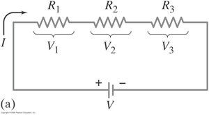
Series Connection: Resistors are connected end-to-end, so the current is the same through each resistor. The total resistance is the sum of individual resistances: \( R_{\text{total}} = R_1 + R_2 + R_3 + \ldots \).
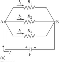
Parallel Connection: Resistors are connected across the same two points, so the voltage across each is the same. The total resistance is given by: \( \frac{1}{R_{\text{total}}} = \frac{1}{R_1} + \frac{1}{R_2} + \frac{1}{R_3} + \ldots \).
Example: Three resistors of 2 \Omega, 3 \Omega, and 6 \Omega in series have a total resistance of 11 \Omega. In parallel, the total resistance is \( 1/(1/2 + 1/3 + 1/6) = 1 \Omega \).
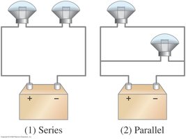
Conceptual Example: Series or Parallel?
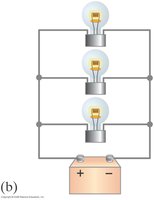
Comparing series and parallel configurations helps understand their practical effects, such as brightness of bulbs or wiring in vehicles.
Series: Bulbs share the same current; if one fails, all go out. Brightness is less because the current is divided among all bulbs.
Parallel: Each bulb receives the full voltage; if one fails, others remain lit. Bulbs are brighter.
Application: Car headlights are wired in parallel to ensure both work independently and at full brightness.
Example: Circuit with Series and Parallel Resistors
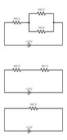
Analyzing circuits with both series and parallel resistors requires calculating equivalent resistance and using Ohm's law to find current.
Step 1: Identify series and parallel sections.
Step 2: Calculate equivalent resistance for each section.
Step 3: Use \( I = \frac{V}{R_{\text{total}}} \) to find total current.
Example: If a 12 V battery is connected to a circuit with a 400 \Omega resistor in series with a parallel combination of 500 \Omega and 250 \Omega, find the total current.
Kirchhoff’s Rules
For complex circuits that cannot be simplified into series and parallel, Kirchhoff’s rules are used. These rules are based on conservation of charge and energy.
Junction Rule: The sum of currents entering a junction equals the sum leaving it (conservation of charge).
Loop Rule: The sum of potential differences around any closed loop is zero (conservation of energy).
Application: Assign current directions, write equations for each junction and loop, and solve the system.
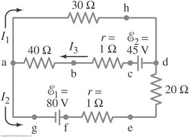
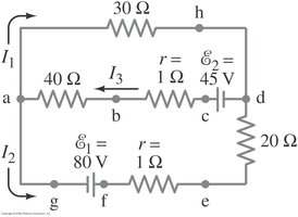
Example: Using Kirchhoff’s Rules
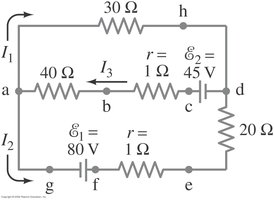
Kirchhoff’s rules allow calculation of unknown currents in multi-loop circuits. Assign current directions and write equations for each loop and junction.
Step 1: Label each current and its direction.
Step 2: Apply junction and loop rules to write equations.
Step 3: Solve the system of equations.
Example: Calculate \( I_1, I_2, I_3 \) in a circuit with two batteries and three branches.
Sign Conventions in Kirchhoff’s Rules
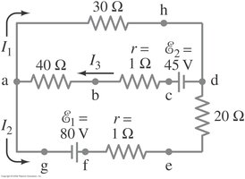
Correct sign conventions are essential for applying Kirchhoff’s rules:
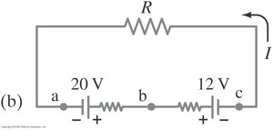
Battery: Voltage increases from negative to positive terminal; decreases from positive to negative.
Resistor: Voltage drops in the direction of current flow; rises opposite to current.
Capacitor: Follows battery terminal directions; current is zero in steady state.
Series and Parallel EMFs; Battery Charging
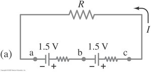
Batteries can be connected in series or parallel to increase voltage or current capacity. The direction of EMFs affects the total voltage and charging behavior.
Series, Same Direction: Total voltage is the sum of individual EMFs.
Series, Opposite Direction: Total voltage is the difference; the lower-voltage battery may be charged by the higher-voltage battery.
Circuits Containing Resistor and Capacitor (RC Circuits)
RC circuits involve a resistor and a capacitor, and are fundamental for understanding time-dependent behavior in circuits. Charging and discharging a capacitor follows exponential laws governed by ordinary differential equations.
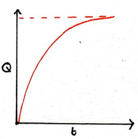
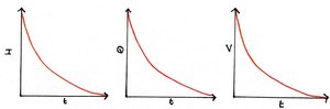
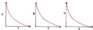
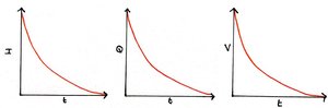
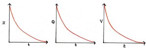
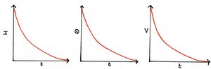
Charging: When a capacitor is charged, the voltage across it increases exponentially, while the current decreases exponentially.
Discharging: When a capacitor discharges, the voltage and current decrease exponentially.
Time Constant (\( \tau \)): \( \tau = RC \), where \( R \) is resistance and \( C \) is capacitance. It characterizes the rate of charging/discharging.
Equations:
Charging: \( Q(t) = Q_0 \left(1 - e^{-t/RC}\right) \)
Discharging: \( Q(t) = Q_0 e^{-t/RC} \)
Current: \( I(t) = \frac{V_0}{R} e^{-t/RC} \)
Example: In a circuit with \( R = 1 \Omega \) and \( C = 1 \mu F \), the time constant is \( 1 \times 1 \times 10^{-6} = 1 \mu s \).
Conceptual Example: Bulb in RC Circuit
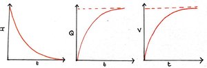
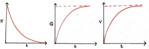
When a bulb is placed in an RC circuit, its brightness changes as the capacitor charges. Initially, the bulb is bright as current flows; over time, the brightness decreases as the current drops and the capacitor approaches full charge.
Initial: Bulb is bright; current is maximum.
Long Time Later: Bulb dims and eventually goes out as current approaches zero.
