 뒤로
Electric Circuits II: Series and Parallel Circuits, Kirchhoff’s Rules, and Ohm’s Law
스터디 가이드 - 스마트 노트
 자료에 맞춘 맞춤형 노트, 핵심 정의, 예시, 맥락을 확장해 제공합니다.
Electric Circuits II
Series and Parallel Circuits
Electric circuits can be constructed by connecting resistors (or bulbs) in series or parallel. The arrangement affects the total resistance, current distribution, and voltage drops in the circuit.
Series Connection: All elements are connected end-to-end, so the same current flows through each element. The total resistance increases as more elements are added.
Parallel Connection: Elements are connected across the same two points, providing multiple paths for current. The total resistance decreases as more elements are added.
Formulas:
Series:
Parallel:
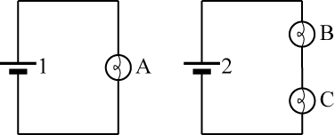
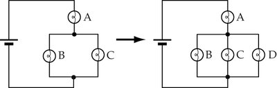
Current, Resistance, and Brightness in Circuits
The brightness of a light bulb in a circuit is determined by the power it dissipates, which depends on both the current through and the voltage across the bulb. Adding resistors in series increases the total resistance and decreases the current, while adding them in parallel decreases the total resistance and increases the current from the battery.
Power dissipated by a bulb:
Series: Same current through all bulbs; voltage divides according to resistance.
Parallel: Same voltage across all bulbs; current divides according to resistance.
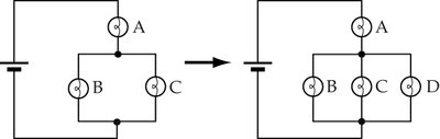
Potential Difference and Voltage Drops
A battery provides a constant potential difference (voltage) between its terminals. As charge moves through resistors, it loses potential energy, which is converted to other forms (e.g., heat, light). The sum of voltage drops across all elements in a closed loop equals the battery voltage.
Voltage drop across a resistor:
In series: Voltage divides among resistors.
In parallel: Each branch experiences the same voltage drop.
Using Voltmeters
A voltmeter measures the potential difference across a circuit element. It must be connected in parallel with the element to measure the voltage drop correctly.

Kirchhoff’s Loop Rule
Kirchhoff’s loop rule states that the sum of the potential differences (voltage) around any closed loop in a circuit must be zero. This is a consequence of energy conservation.
Mathematical statement:
For a loop containing a battery and resistors:
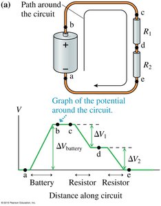
Ohm’s Law and Resistance
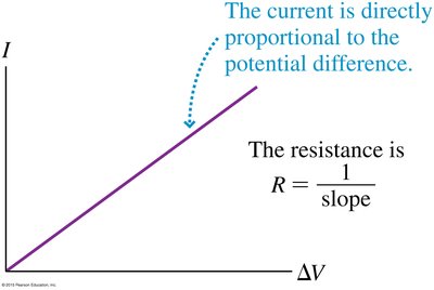
Ohm’s law describes the linear relationship between the current through a resistor and the voltage across it, provided the resistance remains constant (Ohmic materials).
Ohm’s Law:
Resistance:
For non-Ohmic materials, resistance changes with voltage or current.
Comparing Bulb Brightness in Circuits
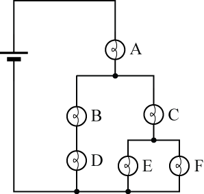
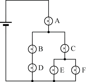
To compare the brightness of bulbs in complex circuits, consider both the current through and the voltage across each bulb. For identical bulbs:
In series: The bulb with higher resistance gets a larger voltage drop and is brighter.
In parallel: All bulbs have the same voltage; the bulb with lower resistance gets more current and is brighter.
Problem-Solving Strategies for Circuits
To analyze electric circuits, follow these steps:
Find the equivalent resistance () for the entire circuit.
Use Ohm’s law to relate the battery voltage, total current, and equivalent resistance:
Use Ohm’s law to find the voltage across resistors that receive all the battery’s current.
Apply Kirchhoff’s loop rule to find voltage drops across other sections.
Use Ohm’s law to find the current through any resistor with a known voltage drop.
Summary Table: Series vs. Parallel Circuits
Property | Series | Parallel |
|---|---|---|
Current | Same through all elements | Divides among branches |
Voltage | Divides among elements | Same across all branches |
Resistance | Adds: | Reciprocal sum: |
Effect of Adding Resistor | Increases | Decreases |
