 뒤로
뒤로Electric Current and Resistance: Physics with Calculus Study Notes
스터디 가이드 - 스마트 노트
 자료에 맞춘 맞춤형 노트, 핵심 정의, 예시, 맥락을 확장해 제공합니다.
Electric Current
Definition and Fundamental Concepts
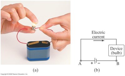
Electric current is the flow of electric charge through a conductor, typically driven by a potential difference (voltage) applied across the conductor. The presence of an electric field within the conductor is necessary to move charges.
Electric Current (I): Defined as the rate of flow of charge. (average current), (instantaneous current)
Unit: Ampère (A), where
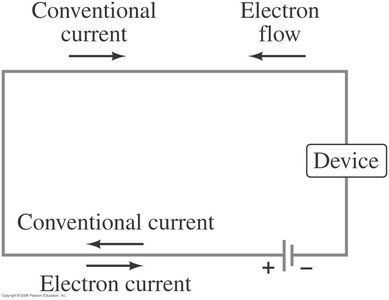
Conventional Current: Direction is from positive to negative terminal (movement of positive charge).
Electron Flow: Actual movement of electrons is from negative to positive terminal.
Microscopic Description of Current
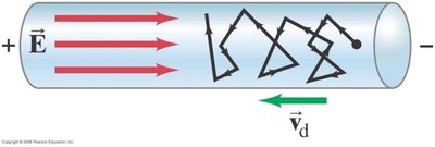
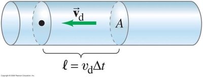
On a microscopic scale, current is due to the drift of free electrons in a conductor under the influence of an electric field. Electrons move randomly but acquire a net drift velocity opposite to the electric field.
Drift Velocity (): Average velocity of charge carriers due to the electric field.
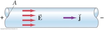
Current Density (): Current per unit area, directed along the electric field.
Ohm's Law
Relationship Between Current and Voltage
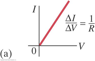
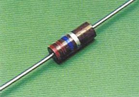
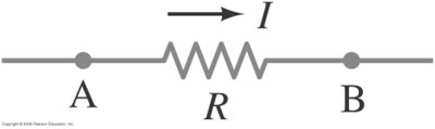
Ohm's Law states that the current through a conductor is directly proportional to the voltage across it, provided the temperature remains constant. The proportionality constant is the resistance.
Ohm's Law:
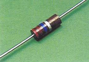
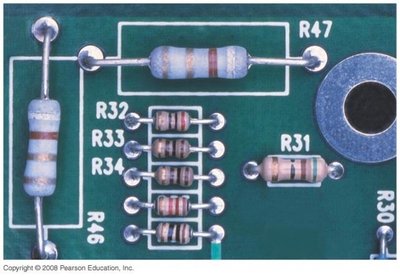
Resistance (R): A measure of how much a material opposes the flow of current. Unit: Ohm (), where
Ohmic Materials: Materials with constant resistance (linear - relationship).
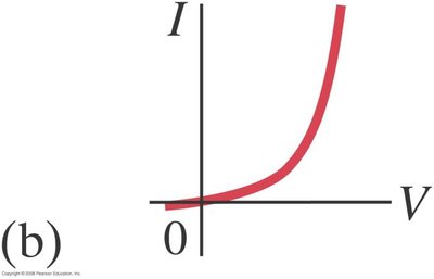
Non-Ohmic Materials: Resistance varies with voltage (e.g., diodes).
Resistance and Resistivity
Factors Affecting Resistance
The resistance of a conductor depends on its material, length, and cross-sectional area. The intrinsic property of the material is called resistivity ().
Formula:
Resistivity (): Characteristic of the material, independent of geometry. Unit:
Length (): Resistance increases with length.
Area (): Resistance decreases with increasing cross-sectional area.
Temperature Dependence of Resistivity
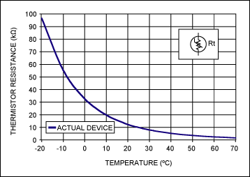
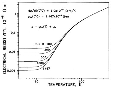
Resistivity changes with temperature, typically increasing for metals and decreasing for semiconductors.
Metals:
Semiconductors: Resistivity decreases with increasing temperature.
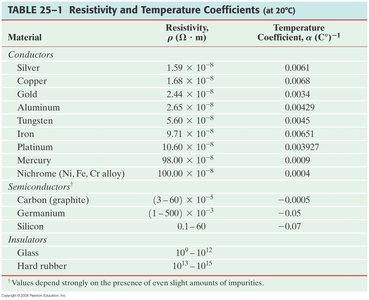
Material | Resistivity () | Temperature Coefficient () |
|---|---|---|
Silver | 0.0061 | |
Copper | 0.0068 | |
Gold | 0.0034 | |
Aluminum | 0.00429 | |
Carbon (graphite) | -0.0005 | |
Silicon | -0.07 | |
Glass | -- |
Electric Power and Joule's Law
Conversion of Electrical Energy
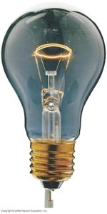
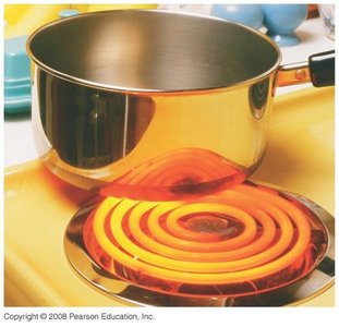
Electric power is the rate at which electrical energy is converted into other forms, such as heat or light. In resistive elements, power is dissipated as heat due to collisions between electrons and atoms.
Power Formula:
Joule's Law: Describes the heating effect in resistors.
Applications: Light bulbs, heating elements.
Resistors in Series and Parallel
Series Connection
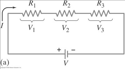
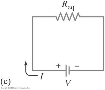
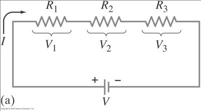
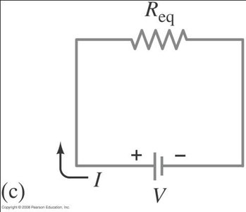
When resistors are connected in series, the same current flows through each, and the total voltage is the sum of individual voltages. The equivalent resistance increases.
Series Formula:
Current: Same through all resistors.
Voltage:
Parallel Connection
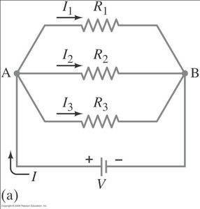
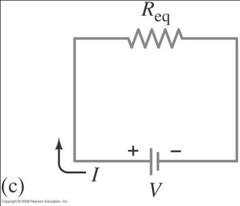
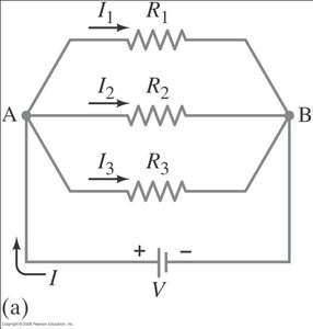
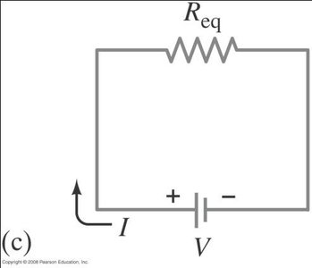
In parallel, the voltage across each resistor is the same, but the total current is the sum of the currents through each branch. The equivalent resistance decreases.
Parallel Formula:
Current:
Voltage: Same across all resistors.
Applications and Safety Devices
Household Circuits and Fuses
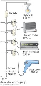
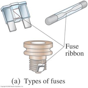
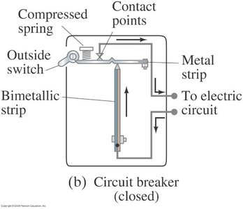
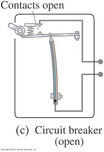
Household electrical circuits often require large currents. To prevent overheating and potential fire hazards, safety devices such as fuses and circuit breakers are used.
Fuse: A device that melts and breaks the circuit if the current exceeds a safe value.
Circuit Breaker: An automatic switch that opens the circuit when excessive current is detected.
Batteries and Electromotive Force (emf)
Chemical Origin of emf
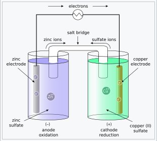
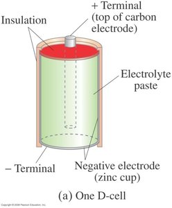
Batteries convert chemical energy into electrical energy, creating a potential difference between terminals. The electromotive force (emf) is the energy per unit charge supplied by the battery.
emf ():
Internal Resistance: Real batteries have internal resistance (), causing a voltage drop when current flows.
Terminal Voltage:
Type | Energy Conversion | Example |
|---|---|---|
Electrochemical Cell | Chemical to Electrical | Zn-Cu cell |
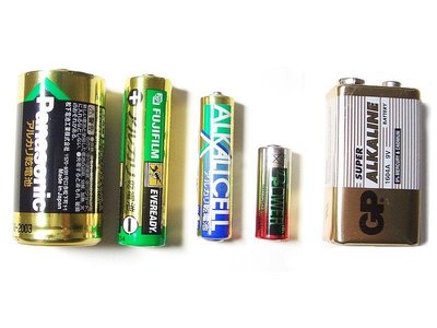
Dry Cell | Chemical to Electrical | Alkaline battery |
Summary Table: Key Equations
Concept | Equation |
|---|---|
Current | |
Ohm's Law | |
Resistance | |
Power | |
Series Resistors | |
Parallel Resistors | |
emf | |
Terminal Voltage |
Additional info: Academic context and examples have been expanded for clarity and completeness. All images included are directly relevant to the adjacent explanations.
