뒤로
뒤로Electromagnetic Induction, AC Circuits, and Wave Optics: Study Notes
스터디 가이드 - 스마트 노트
 자료에 맞춘 맞춤형 노트, 핵심 정의, 예시, 맥락을 확장해 제공합니다.
Mutual Inductance and Self-Inductance
Mutual Inductance
Mutual inductance describes the phenomenon where a changing current in one coil induces an electromotive force (emf) in a nearby coil. This is a fundamental principle behind transformers and wireless charging systems.
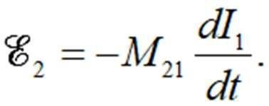
Mutual Inductance (M): The proportionality constant relating the induced emf in one coil to the rate of change of current in another coil.
Formula for Induced emf:
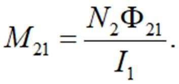
Definition of Mutual Inductance:
Unit: Henry (H), where .
Applications: Transformers, wireless chargers, and rechargeable batteries.
Self-Inductance
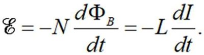
Self-inductance is the property of a coil (or circuit) to induce an emf in itself when the current through it changes. The proportionality constant is called the self-inductance (L).
Formula for Self-Induced emf:
Definition of Self-Inductance:
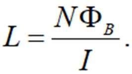
Physical Meaning: L measures how effectively a coil induces emf in itself due to a changing current.
LR Circuits (Inductor-Resistor Circuits)
Current Growth and Decay in LR Circuits
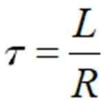
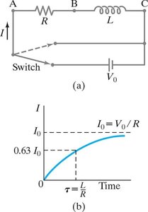
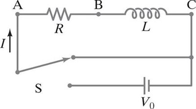
When a circuit contains both an inductor (L) and a resistor (R), the current does not immediately reach its maximum value when the circuit is closed. Instead, it increases gradually, characterized by a time constant .
Time Constant:
Current Growth: The current increases exponentially toward its maximum value .
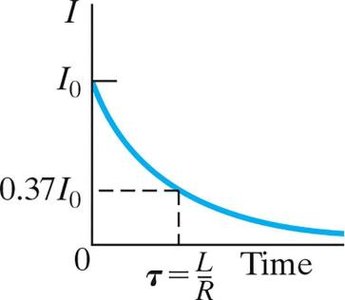
Current Decay: When the circuit is opened, the current decreases exponentially.
Example Circuit:
LC and LRC Circuits
LC Circuits and Electromagnetic Oscillations
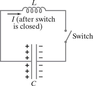
An LC circuit consists of an inductor (L) and a capacitor (C) connected together. When the capacitor is charged and the switch is closed, the circuit exhibits oscillatory behavior similar to simple harmonic motion.
Oscillations: Charge and current oscillate sinusoidally, with energy transferring between the electric field of the capacitor and the magnetic field of the inductor.
Idealization: Real circuits always have some resistance, but the pure LC circuit is a useful model.
LRC Circuits (Damped Oscillations)
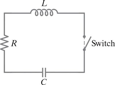
When resistance (R) is included with L and C, the circuit is called an LRC circuit. The oscillations are damped, and the behavior depends on the relative values of R, L, and C.
Three Cases:
Underdamped: (oscillatory decay)
Overdamped: (no oscillation, slow return to equilibrium)
Critically damped: (fastest return to equilibrium without oscillation)
AC Circuits: Reactance, Impedance, and Phasors
Reactance and Impedance
In AC circuits, inductors and capacitors introduce reactance, which opposes the flow of alternating current. The total opposition to current is called impedance (Z).
Inductive Reactance: (current lags voltage by )
Capacitive Reactance: (current leads voltage by )
Impedance:
Phasor Diagrams
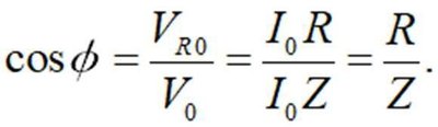
Phasors are rotating vectors used to represent the voltages and currents in AC circuits. The phase angle between the total voltage and current is given by:

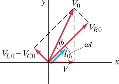
Power Factor:
Resonance in AC Circuits
Resonance occurs in an LRC circuit when the inductive and capacitive reactances are equal (), resulting in the impedance being purely resistive and the current reaching its maximum value.
Resonant Angular Frequency:

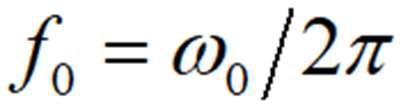
Resonant Frequency:
Filters
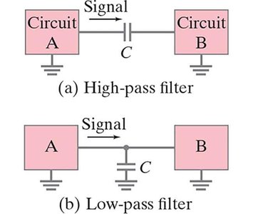
Filters are circuits that allow certain frequencies to pass while blocking others.
High-pass filter: Allows AC signals to pass but blocks DC voltage.
Low-pass filter: Allows DC voltage to pass but blocks higher-frequency AC signals.
Three-Phase AC Power
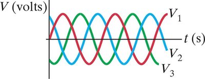
Three-phase AC power is commonly used in power transmission because it provides smoother and more efficient power delivery than single-phase systems. The three voltages are separated by in phase.
Maxwell's Equations and Electromagnetic Waves
Maxwell's Equations (Integral Form)
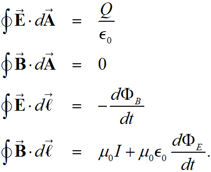
Maxwell's equations summarize the fundamental laws of electricity and magnetism. In the absence of dielectric or magnetic materials, they are:
Gauss's Law for Electricity
Gauss's Law for Magnetism
Faraday's Law of Induction
Ampère-Maxwell Law
Electromagnetic Waves
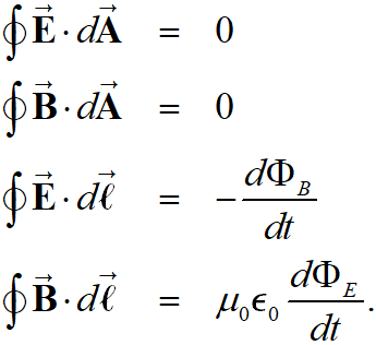
Maxwell's equations predict that changing electric and magnetic fields can propagate through space as electromagnetic waves. These waves are self-sustaining and travel at the speed of light.
Key Properties:
Electric and magnetic fields are perpendicular to each other and to the direction of propagation.
They are in phase with each other.
The Electromagnetic Spectrum
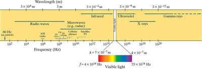
The electromagnetic spectrum encompasses all possible frequencies of electromagnetic waves, from radio waves to gamma rays. Visible light is only a small part of the spectrum.
Geometric Optics: Mirrors and Lenses
Ray Diagrams for Spherical Mirrors
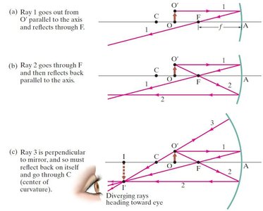
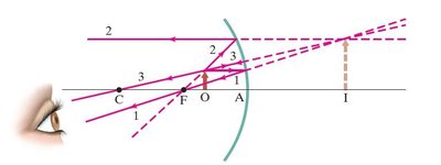
Ray diagrams are used to determine the position and nature of images formed by mirrors. For concave mirrors, three principal rays are used:
Ray parallel to axis reflects through focal point.
Ray through focal point reflects parallel to axis.
Ray through center of curvature reflects back on itself.
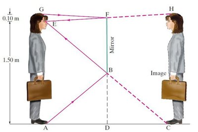
Plane Mirror Image Formation
In a plane mirror, the image is virtual, upright, and the same size as the object. The minimum height of a mirror required to see the full body is half the person's height.
Ray Diagram for Object Inside Focal Point (Concave Mirror)
If the object is placed between the focal point and the mirror, the image is virtual, upright, and enlarged.
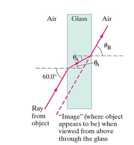
Refraction: Snell's Law
When light passes from one medium to another, it bends according to Snell's Law:
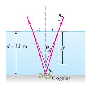
Apparent Depth in Water
Objects under water appear shallower than they actually are due to refraction at the water surface.
Thin Lenses and Ray Tracing
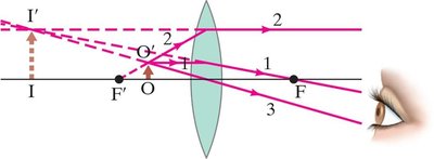
Ray Diagrams for Thin Lenses
For thin lenses, three principal rays are used to locate the image:
Ray parallel to axis refracts through focal point.
Ray through focal point refracts parallel to axis.
Ray through center of lens passes straight through.
Combinations of Lenses
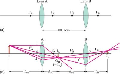
When two or more lenses are used in combination, the image formed by the first lens becomes the object for the second lens. The total magnification is the product of the individual magnifications.
Measuring Focal Length of a Diverging Lens
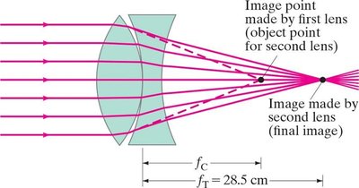
The focal length of a diverging lens can be measured by combining it with a converging lens and focusing parallel rays.
Lensmaker's Equation Example
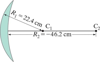
The focal length of a lens depends on the radii of curvature of its surfaces and the index of refraction of the material.
Wave Optics: Interference and Diffraction
Young's Double-Slit Experiment
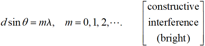
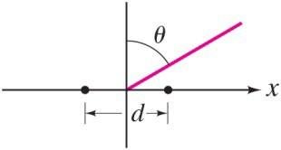
When light passes through two closely spaced slits, it produces an interference pattern of bright and dark fringes on a screen. The condition for constructive interference (bright fringes) is:
For destructive interference (dark fringes):
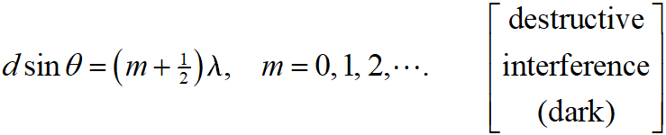
Diagram:
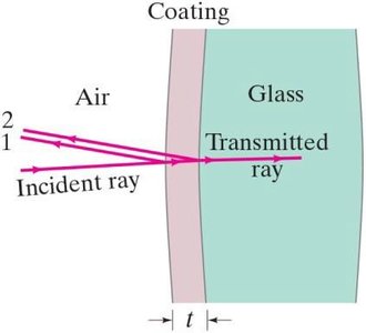
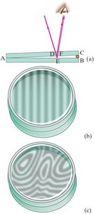
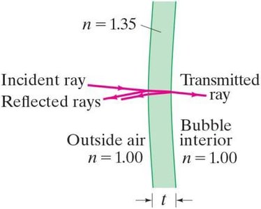
Thin Film Interference
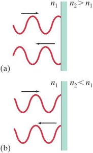
Interference can also occur in thin films, such as soap bubbles or oil slicks, due to the phase difference between light reflected from the top and bottom surfaces of the film.
Polarization
Polarization of Light
Light is polarized when its electric field oscillates in a single plane. Polarizers are materials that only transmit light polarized in a certain direction.
Unpolarized light passing through a polarizer is reduced in intensity by half.
At Brewster's angle, reflected light is completely polarized.