 뒤로
뒤로Fundamentals of Electric Circuits: Series and Parallel Resistor Networks
스터디 가이드 - 스마트 노트
 자료에 맞춘 맞춤형 노트, 핵심 정의, 예시, 맥락을 확장해 제공합니다.
Fundamentals of Circuits
Introduction to Electric Circuits
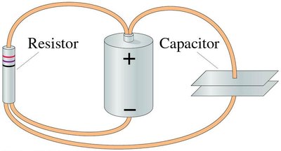
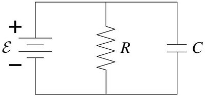
Electric circuits are foundational to understanding how electrical energy is transferred and utilized in physical systems. A circuit consists of various elements such as batteries, resistors, capacitors, and connecting wires, which together form a closed path for current flow.
Circuit Diagram: A schematic representation using symbols to show the connections and relationships between circuit elements.
Physical Circuit: The actual arrangement of components and wires.
Key Elements: Battery (source of emf), resistor (limits current), capacitor (stores charge), wire (conducts current).
Circuit Symbols
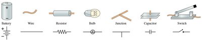
Circuit diagrams use standardized symbols to represent components, making analysis and communication easier.
Battery: Long and short lines, longer line is positive terminal.
Resistor: Zigzag line.
Capacitor: Parallel lines.
Wire: Straight line.
Bulb: Circle with filament.
Switch: Break in line with lever.
Basic Circuit Principles
Complete vs. Incomplete Circuits
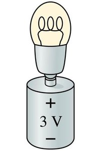
A complete circuit forms a continuous path for current to flow from the battery's positive terminal, through circuit elements, and back to the negative terminal. An incomplete circuit prevents current flow, so devices like bulbs will not light.
Kirchhoff’s Laws
Kirchhoff’s laws are fundamental for analyzing complex circuits:
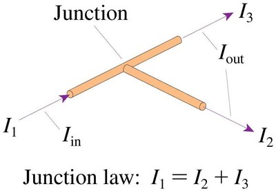
Kirchhoff’s Junction Law: The total current entering a junction equals the total current leaving it. This is a statement of conservation of charge.
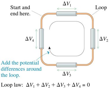
Kirchhoff’s Loop Law: The sum of all potential differences around any closed loop is zero, reflecting conservation of energy.
Applying Kirchhoff’s Loop Law
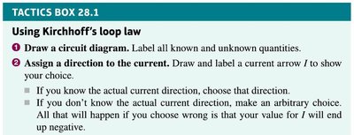
To analyze circuits using Kirchhoff’s loop law:
Draw a circuit diagram and label all known and unknown quantities.
Assign a direction to the current.
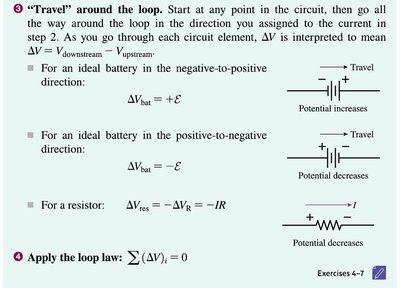
Travel around the loop, summing potential differences.
Apply the loop law:
Series and Parallel Circuits
Series Resistors
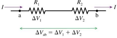
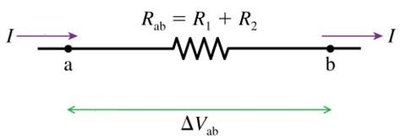
Resistors in series are connected end-to-end, so the same current flows through each. The total resistance is the sum of individual resistances:
Equivalent Resistance:
Potential Difference:
Parallel Resistors
Resistors in parallel are connected at both ends, so the same potential difference is across each, but the current divides among them. The equivalent resistance is given by:
Equivalent Resistance:
Current Division:
Energy and Power in Circuits
Power Supplied and Dissipated
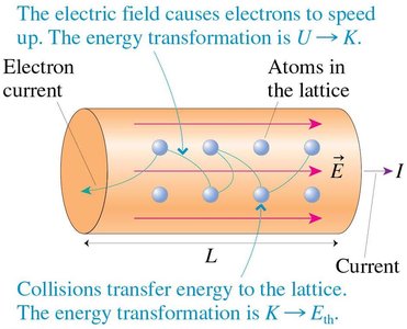
Power in circuits is the rate at which energy is transferred or converted. Batteries supply power, and resistors dissipate it as heat.
Power supplied by battery:
Power dissipated by resistor:
Kilowatt Hours
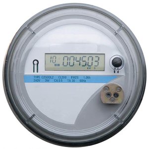
Energy usage is often measured in kilowatt-hours (kWh), where 1 kWh = 3.6 × 10⁶ J. This unit is commonly used by electric companies to bill customers.
Example: A 4000 W heater running for 10 hours uses 40 kWh.
Cost Calculation: Multiply kWh by the rate per kWh.
Measurement Devices
Ammeters and Voltmeters
Ammeters measure current and are connected in series with negligible resistance. Voltmeters measure potential difference and are connected in parallel with very high resistance to avoid drawing current.
Ammeters: Inserted in series, resistance is nearly zero.
Voltmeters: Connected in parallel, resistance is very high.
Example Problems and Applications
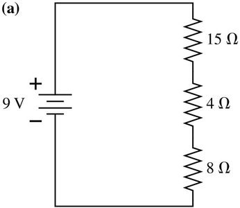
Example: Series Resistor Circuit
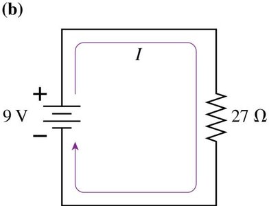
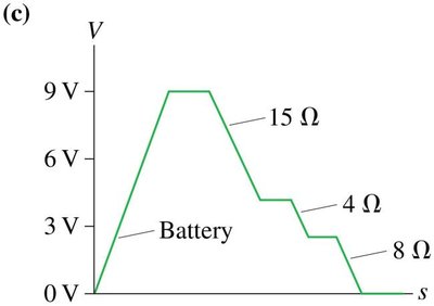
Three resistors (15 Ω, 4 Ω, 8 Ω) in series with a 9 V battery:
Equivalent Resistance:
Current:
Potential Drops: Across each resistor, calculated as
Example: Parallel Resistor Circuit
Three resistors (15 Ω, 4 Ω, 8 Ω) in parallel with a 9 V battery:
Equivalent Resistance:
Current:
Current Division: Each resistor gets a different current,
Summary Table: Series vs. Parallel Resistors
Property | Series | Parallel |
|---|---|---|
Current | Same through all | Divides among branches |
Potential Difference | Divides among resistors | Same across all |
Equivalent Resistance |
Additional info: These notes expand on brief points from the slides, providing full academic context, definitions, and examples for self-contained study.
