 뒤로
뒤로Inductance, Electromagnetic Oscillations, and AC Circuits: Study Notes
스터디 가이드 - 스마트 노트
 자료에 맞춘 맞춤형 노트, 핵심 정의, 예시, 맥락을 확장해 제공합니다.
Inductance, Electromagnetic Oscillations, and AC Circuits
Mutual Inductance
Mutual inductance describes the phenomenon where a changing current in one coil induces an electromotive force (emf) in a second coil. This effect is fundamental to the operation of transformers and coupled circuits.
Definition: The mutual inductance M between two coils is defined by the induced emf in coil 2 due to a changing current in coil 1:
Symmetry: The mutual inductance is the same regardless of which coil is the source:
Unit: The unit of inductance is the henry (H):
Dependence: For fixed coils, M depends only on geometric properties (number of turns, area, relative position).
Example (Solenoid and Coil): For a solenoid of length , area , turns, and a surrounding coil of turns:
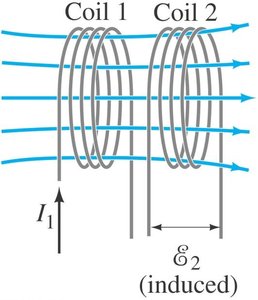
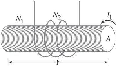
Self-Inductance
Self-inductance is the property of a coil (or any circuit) to induce an emf in itself when the current through it changes. This is the basis for the operation of inductors.
Definition: The self-induced emf is , where is the self-inductance.
Formula: , where is the magnetic flux through each turn.
Solenoid Example: For a long solenoid with turns, length , and area :
Direction of emf: The induced emf always opposes the change in current (Lenz's Law).
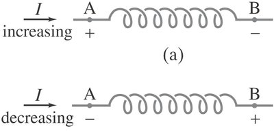
Inductance of a Coaxial Cable
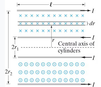
The inductance per unit length of a coaxial cable can be derived by considering the magnetic flux between the inner and outer conductors.
Formula: , where and are the radii of the inner and outer conductors, respectively.
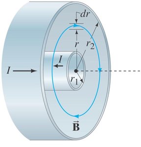
Energy Stored in a Magnetic Field
Inductors store energy in their magnetic fields. The energy supplied to an inductor is stored as magnetic energy.
Power supplied:
Energy stored:
Energy density in a solenoid:
LR Circuits
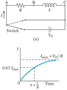
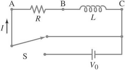
An LR circuit consists of an inductor and a resistor in series with a voltage source. The current in the circuit changes over time as the inductor resists changes in current.
Differential equation:
Solution (current as a function of time): , where is the time constant.
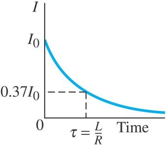
Decay after disconnecting the battery:
LC Circuits and Electromagnetic Oscillations
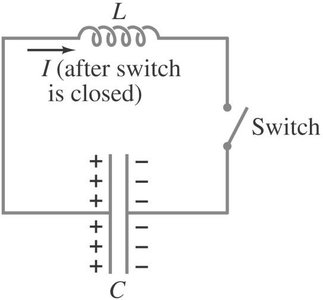
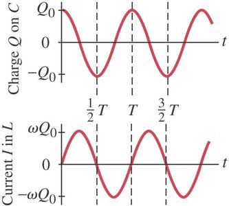
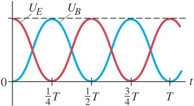
An LC circuit consists of an inductor and a capacitor. When the capacitor is initially charged and the circuit is closed, the charge and current oscillate sinusoidally, analogous to a mass-spring system.
Differential equation:
Solution: ,
Angular frequency:
Total energy: (constant)
LRC Circuits (Damped Oscillations)
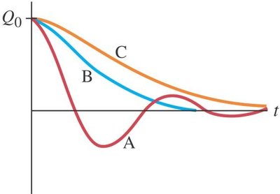
In real circuits, resistance is always present, leading to damped oscillations. The LRC circuit is described by a second-order differential equation similar to a damped harmonic oscillator.
Differential equation:
Solution (underdamped): , where
Cases:
Underdamped (): Oscillatory decay
Critically damped (): Fastest non-oscillatory decay
Overdamped (): Slow non-oscillatory decay
Complex Impedance in AC Circuits
For AC circuits, the concept of impedance generalizes resistance to include capacitors and inductors, using complex numbers to account for phase differences.
Impedance of a resistor:
Impedance of an inductor:
Impedance of a capacitor:
Phase relationships: In an inductor, voltage leads current by ; in a capacitor, voltage lags current by $\frac{\pi}{2}$.
LRC Series and Parallel Circuits
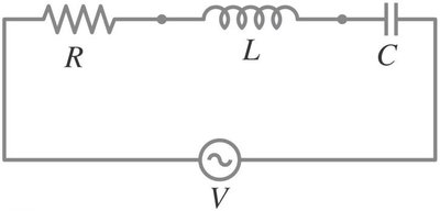
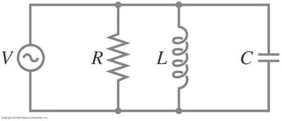
For a series LRC circuit, the total impedance is the sum of the individual impedances. For a parallel LRC circuit, the reciprocals of the impedances add.
Series:
Current:
Resonance: Maximum current occurs at
Parallel:
Passive Analog Filters
Filters are circuits that selectively pass or attenuate signals of different frequencies. They are characterized by their transfer function , which describes the ratio of output to input voltage as a function of frequency.
Voltage divider (generalized):
Transfer function:
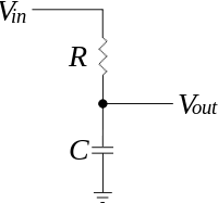
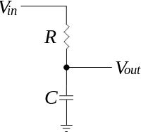
Low Pass RC Filter
A low pass filter allows low-frequency signals to pass while attenuating high-frequency signals.
Transfer function:
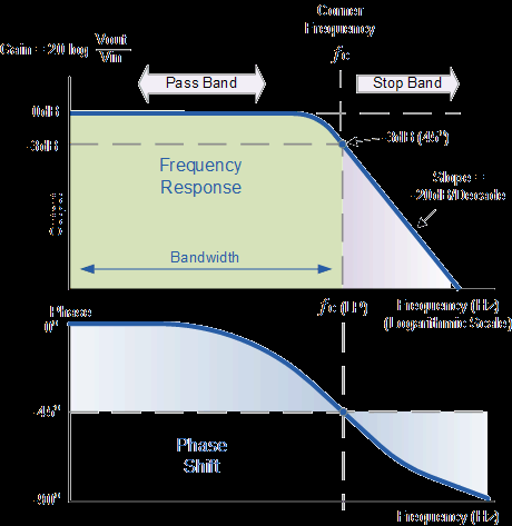
Magnitude:
Phase:
Cutoff frequency: (at which )
Attenuation: Output decreases by 20 dB per decade above cutoff frequency.
High Pass RC Filter
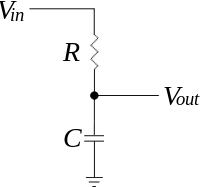
A high pass filter allows high-frequency signals to pass while attenuating low-frequency signals.
Transfer function:
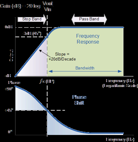
Magnitude:
Phase:
Cutoff frequency:
Attenuation: Output increases by 20 dB per decade below cutoff frequency.
Band-Pass and Band-Stop Filters
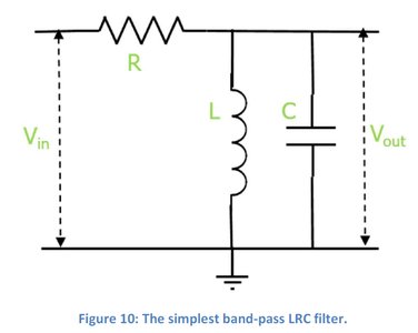
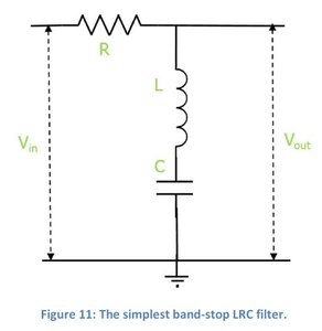
Band-pass filters allow a specific range of frequencies to pass, while band-stop filters attenuate a specific range. These are typically implemented using LRC circuits.
Band-pass: Passes frequencies near resonance
Band-stop: Attenuates frequencies near resonance
Physical Meaning of Complex Impedance
The real part of impedance (resistance) dissipates energy, while the imaginary part (reactance) stores energy in electric or magnetic fields. In AC circuits, this leads to phase differences between voltage and current.
Resistor: Power is always dissipated as heat.
Inductor/Capacitor: Power alternates between storage and release, with zero average over a cycle.
Summary Table: Impedance of Basic Circuit Elements
Element | Impedance | Phase Relationship |
|---|---|---|
Resistor () | Voltage and current in phase | |
Inductor () | Voltage leads current by | |
Capacitor () | Voltage lags current by |
