 뒤로
뒤로Magnetic Force on Current-Carrying Conductors and Applications
스터디 가이드 - 스마트 노트
 자료에 맞춘 맞춤형 노트, 핵심 정의, 예시, 맥락을 확장해 제공합니다.
Magnetic Force on Current-Carrying Conductors
Introduction
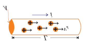
When an electric current flows through a conductor placed in a magnetic field, the conductor experiences a force due to the interaction between the magnetic field and the moving charges. This phenomenon is fundamental to the operation of many electrical devices, including electric motors, galvanometers, and the Hall effect sensor.
Magnetic Force on a Current-Carrying Conductor
Definition: The force experienced by a conductor carrying current in a magnetic field is called the magnetic force.
Origin: The force arises because the moving charges (current) in the wire interact with the external magnetic field.
Formula (Maximum Force): When the magnetic field is perpendicular to the current, the force is given by: where:
B = magnetic field strength (in tesla, T)
I = current (in amperes, A)
L = length of the conductor in the field (in meters, m)
General Case (Angle θ): If the conductor makes an angle θ with the magnetic field: where θ is the angle between the direction of current and the magnetic field.
Direction: The direction of the force is given by the right-hand rule: point your fingers in the direction of current, curl them toward the magnetic field, and your thumb points in the direction of the force.
Example: Force on a Wire in a Magnetic Field
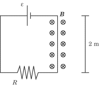
Given: A wire of length 2 m, resistance 5 Ω, voltage 30 V, placed perpendicular to a magnetic field of 0.5 T.
Solution:
Calculate current using Ohm's Law:
Apply the force formula:
Magnitude and Direction of the Force
Maximum Force: When the conductor is perpendicular to the field (), .
No Force: When the conductor is parallel to the field (), .
Right-Hand Rule: Used to determine the direction of the force relative to the current and magnetic field.
Torque on a Current Loop
Torque in a Uniform Magnetic Field
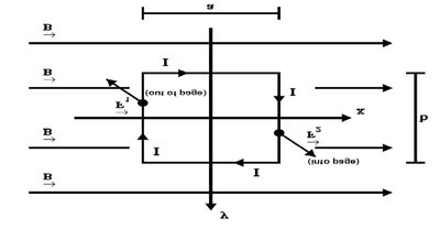
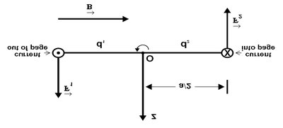
A current loop in a uniform magnetic field experiences a torque that tends to rotate the loop. This principle is the basis for electric motors.
Formula for Torque: where:
\tau = torque (N·m)
B = magnetic field strength (T)
I = current (A)
A = area of the loop (m²)
\theta = angle between the normal to the loop and the magnetic field
Multiple Turns: For a coil with N turns:
Magnetic Dipole Moment: , so
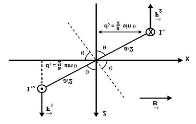
Example: Torque on a Circular Loop
Given: Current mA, circumference m, T, .
Area: , where is the circumference.
Torque: (with for maximum torque).
Applications of Magnetic Force
Galvanometers
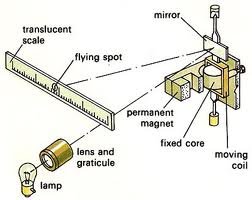
A galvanometer is a sensitive instrument used to detect and measure small electric currents. It operates on the principle that a current-carrying coil in a magnetic field experiences a torque, causing a pointer to move over a scale.
Key Components: Moving coil, permanent magnet, scale, pointer.
Operation: The deflection of the pointer is proportional to the current passing through the coil.
Electric Motors
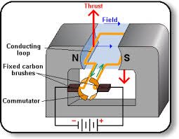
Electric motors convert electrical energy into mechanical rotation using the torque produced on a current-carrying loop in a magnetic field. Continuous rotation is achieved by reversing the current direction every half turn using a commutator and brushes (in DC motors).
Key Principle: The torque on the loop causes rotation; the commutator ensures the torque always acts in the same rotational direction.
Types: DC motors use commutators; AC motors use alternating current to reverse the current direction automatically.
Hall Effect
Principle and Explanation
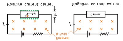
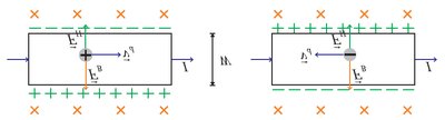
The Hall effect occurs when a current-carrying conductor is placed in a perpendicular magnetic field, causing a voltage (Hall voltage) to develop across the conductor due to the separation of charges.
Cause: The magnetic force pushes charge carriers to one side, creating an electric field (Hall field) that opposes further charge separation.
Equilibrium: The Hall field balances the magnetic force, resulting in a measurable voltage across the conductor.
Hall Voltage Formula: where:
I = current
B = magnetic field strength
n = charge carrier density
q = charge of carrier
A = cross-sectional area
Applications: Used to measure magnetic field strength and determine carrier density in materials.
Summary Table: Key Equations and Concepts
Concept | Equation | Description |
|---|---|---|
Magnetic Force on Wire | Force on a wire of length L carrying current I in field B at angle θ | |
Torque on Loop | Torque on a loop of area A, N turns, current I in field B | |
Hall Voltage | Voltage developed across a conductor due to Hall effect |
Additional info:
The right-hand rule is essential for determining the direction of magnetic forces and torque.
Electric motors and galvanometers are practical applications of the torque on current loops.
The Hall effect is widely used in sensors and material characterization.
