 뒤로
뒤로PHYS 113 - Introduction to Physics II: Review 4 – Step-by-Step Study Guidance
스터디 가이드 - 스마트 노트
 자료에 맞춘 맞춤형 노트, 핵심 정의, 예시, 맥락을 확장해 제공합니다.
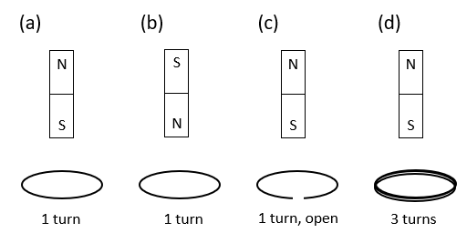
Q3. Four equal-mass magnets are falling by gravity. Order them from least accelerated to most accelerated.
Background
Topic: Electromagnetic Induction and Lenz's Law
This question tests your understanding of how electromagnetic induction affects the motion of magnets falling through conducting loops. The acceleration of each magnet depends on the induced currents and the resulting magnetic forces (Lenz's Law).
Key Terms and Concepts:
Lenz's Law: The direction of induced current in a loop opposes the change in magnetic flux.
Eddy Currents: Circulating currents induced in conductors by changing magnetic fields, which create opposing magnetic fields.
Magnetic Flux ():
Induced emf ():
Step-by-Step Guidance
Examine each configuration: (a), (b), (c), and (d). Consider the number of turns, whether the loop is open or closed, and the orientation of the magnet.
Recall that a closed conducting loop will allow induced currents (eddy currents) to flow, which oppose the motion of the magnet (reducing acceleration). An open loop will not support a current, so there is no opposing force.
Consider the effect of the number of turns: More turns in the loop increase the induced emf and thus the opposing force (greater reduction in acceleration).
Think about the orientation of the magnet: The direction of the magnetic field through the loop matters for the sign of the induced current, but the magnitude of the opposing force depends on the rate of change of flux, not the direction.
Rank the configurations from least to most acceleration based on the strength of the opposing force (no current = greatest acceleration; more turns = least acceleration).
Try solving on your own before revealing the answer!
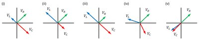
Q6. In the figure below, which of the phasor diagrams represents a series RLC circuit driven at resonance?
Background
Topic: AC Circuits – Resonance in RLC Circuits
This question tests your understanding of the phase relationships between voltages across the resistor (), inductor (), and capacitor () in a series RLC circuit at resonance.
Key Terms and Formulas:
Resonance: Occurs when the inductive reactance equals the capacitive reactance ().
Phasor Diagram: A graphical representation of the phase relationships between voltages and currents in AC circuits.
At resonance: and are equal in magnitude and opposite in phase, so they cancel each other out.
Step-by-Step Guidance
Recall that at resonance, the total voltage across the inductor and capacitor is zero because .
In a phasor diagram, is always in phase with the current, leads the current by 90°, and lags the current by 90°.
Look for the diagram where the vectors for and are equal in length but point in exactly opposite directions, and is along the current axis.
Identify which diagram matches these criteria.
Try solving on your own before revealing the answer!
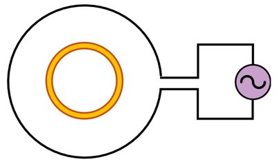
Q7. An outer metal ring surrounds an inner metal ring, as shown in the figure below. If the outer metal ring is connected to an AC power source, what is the direction of the induced current in the inner ring?
Background
Topic: Electromagnetic Induction – Mutual Induction
This question tests your understanding of how a changing current in one loop (due to an AC source) induces a current in a nearby loop, and how the direction of the induced current changes with time.
Key Terms and Concepts:
Mutual Induction: A changing current in one coil induces an emf in a nearby coil.
AC Source: Alternating current changes direction periodically, causing the magnetic field to oscillate.
Lenz's Law: The induced current opposes the change in magnetic flux.
Step-by-Step Guidance
Recognize that the AC source causes the current in the outer ring to alternate, producing a time-varying magnetic field through the inner ring.
Apply Lenz's Law: The induced current in the inner ring will always oppose the change in magnetic flux caused by the outer ring's current.
Since the current in the outer ring alternates, the direction of the induced current in the inner ring will also alternate (periodically changing between clockwise and counterclockwise).
Try solving on your own before revealing the answer!
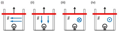
Q8. As shown in the figure below, each metal bar is in contact with a pair of parallel rails and is in motion with an upward velocity of magnitude v. Uniform magnetic fields are applied but their directions differ in each case. Which light-bulb(s) will glow?
Background
Topic: Motional emf and Faraday's Law
This question tests your understanding of how a moving conductor in a magnetic field induces an emf, and under what conditions a current will flow to light a bulb.
Key Terms and Formulas:
Motional emf: (where is the magnetic field, is the length of the bar, is the velocity)
Faraday's Law:
Right-Hand Rule: Determines the direction of induced current based on the direction of motion and magnetic field.
Step-by-Step Guidance
For each setup, determine the direction of the magnetic field and the direction of motion of the bar.
Apply the right-hand rule to find the direction of the induced emf in each case.
Check if the induced emf will cause a current to flow through the bulb (i.e., if the circuit is complete and the emf is nonzero).
Identify which bulbs will glow based on the presence of a current.
Try solving on your own before revealing the answer!
