
Ch. 26 - DC Circuits
Giancoli Douglas - Physics for Scientists and Engineers 5th edition
Giancoli Douglas5th editionPhysics for Scientists and EngineersISBN: 9780137488179당신이 사용하는 게 아니라요?교과서 변경
25장, 문제 26.39

(III) If the 25-Ω resistor in Fig. 26–59 is shorted out (resistance = 0 ), what then would be the current through the 15-Ω resistor?

검증된 단계별 안내
1
Identify the resistors in the circuit and their arrangement. Since the 25-Ω resistor is shorted out, it effectively has no resistance and does not affect the circuit.
Determine the total resistance in the circuit. With the 25-Ω resistor shorted, focus on the remaining resistors. If they are in series, add their resistances directly. If in parallel, use the formula for parallel resistors: \(\frac{1}{R_{total}} = \frac{1}{R_1} + \frac{1}{R_2} + ...\).
Calculate the total voltage supplied in the circuit if not given, assume a standard value or use the given battery voltage.
Apply Ohm's Law, \(V = IR\), to find the total current in the circuit using the total resistance calculated and the total voltage.
To find the current through the 15-Ω resistor specifically, use the current division rule if the resistors are in parallel, or note that the current is the same through each resistor if they are in series.

비슷한 문제에 대한 검증된 영상 답변:

이 영상 해법은 위 문제에 도움이 된다고 튜터들이 추천한 것입니다.
영상 길이:
7m
도움이 되었나요?

주요 개념

질문에 올바르게 답하기 위해 반드시 이해해야 하는 핵심 개념들은 다음과 같습니다.

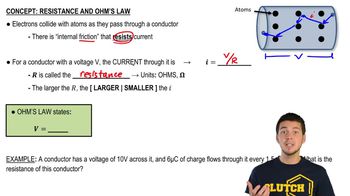
Ohm's Law

Ohm's Law states that the current (I) flowing through a conductor between two points is directly proportional to the voltage (V) across the two points and inversely proportional to the resistance (R) of the conductor. This relationship is expressed mathematically as I = V/R. Understanding this law is crucial for analyzing circuits and determining how current behaves when resistances change.
추천 영상:
가이드 코스
03:07
Resistance and Ohm's Law

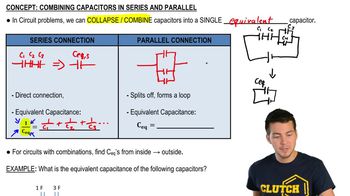
Series and Parallel Circuits

In electrical circuits, components can be arranged in series or parallel configurations. In a series circuit, the current is the same through all components, while in a parallel circuit, the voltage across each component is the same. Knowing how to identify these configurations helps in calculating the total resistance and current flow when components are added or removed, such as shorting a resistor.
추천 영상:
가이드 코스
09:51
Combining Capacitors in Series & Parallel

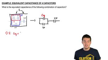
Equivalent Resistance

Equivalent resistance is the total resistance of a circuit when multiple resistors are combined. For resistors in series, the equivalent resistance is the sum of all resistances, while for resistors in parallel, the equivalent resistance can be found using the formula 1/R_eq = 1/R1 + 1/R2 + ... + 1/Rn. This concept is essential for simplifying complex circuits and determining how changes, like shorting a resistor, affect overall current flow.
추천 영상:
가이드 코스
03:44
Find Equivalent Capacitance #1
관련 실천
교과서 질문

[In these Problems neglect the internal resistance of a battery unless the Problem refers to it.]


(II) A power supply has a fixed output voltage of 12.0 V, but you need VT = 3.0 V output for an experiment. (a) Using the voltage divider shown in Fig. 26–47, what should R₂ be if R₁ is 16.5 Ω? (b) What will the terminal voltage VT be if you connect a load to the 3.0-V output, assuming the load has a resistance of 7.0Ω?

141
views
교과서 질문

A voltage V is applied to n identical resistors connected in parallel. If the resistors are instead all connected in series with the applied voltage, show that the power transformed is decreased by a factor n².

1011
views
교과서 질문

(II) Determine the magnitudes and directions of the currents in each resistor shown in Fig. 26–57. The batteries have emfs of ε1 = 9.0V and ε2 = 12.0V and the resistors have values of R1 = 25 Ω, R2 = 48 Ω, and R3 = 35 Ω.

(a) Ignore internal resistance of the batteries.

(b) Assume each battery has internal resistance r = 1.0 Ω.

911
views
교과서 질문

[In these Problems neglect the internal resistance of a battery unless the Problem refers to it.]


(III) You are designing a wire resistance heater to heat an enclosed container of gas. For the apparatus to function properly, this heater must transfer heat to the gas at a very constant rate. While in operation, the resistance of the heater will always be close to the value R = R₀, but may fluctuate slightly causing its resistance to vary a small amount ∆R ( << R₀ ). To maintain the heater at constant power, you design the circuit shown in Fig. 26–50, which includes two resistors, each of resistance R′. Determine the value for R′ so that the heater power P will remain constant even if its resistance R fluctuates by a small amount. [Hint: If ∆R << R₀ , then ΔPΔRdPdRR=R0\(\Delta\) P\(\approx\) \(\Delta\) R\(\left\). \(\frac{dP}{dR}\]\right\)|_{R=R_{0}}]

765
views
교과서 질문

(II) (a) What is the potential difference between points a and d in Fig. 26–55 (similar to Fig. 26–12, Example 26–8), and (b) what is the terminal voltage of each battery?

886
views
교과서 질문

[In these Problems neglect the internal resistance of a battery unless the Problem refers to it.]


(II) What is the net resistance of the circuit connected to the battery in Fig. 26–46?

776
views