


Ch. 28 - Sources of Magnetic Field
Giancoli Douglas - Physics for Scientists and Engineers 5th edition
Giancoli Douglas5th editionPhysics for Scientists and EngineersISBN: 9780137488179당신이 사용하는 게 아니라요?교과서 변경
27장, 문제 79

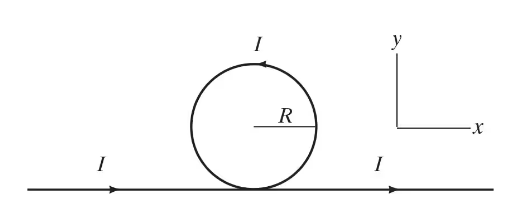
Part of a long, thin insulated straight wire is formed into a single circular loop of radius 𝑅 (Fig. 28–68) and carries a current I. (a) What is the magnitude and direction of the magnetic field at the center of the loop? (b) If the plane of the loop is twisted 90 degrees so that the plane is perpendicular to the straight part of the wire (i.e., in the yz plane) what is the magnitude and direction of the field now at the center of the loop?

검증된 단계별 안내
1
Step 1: Understand the problem and identify the relevant concepts. The problem involves calculating the magnetic field at the center of a circular loop of wire carrying current I. This requires using the Biot-Savart law or Ampere's law for part (a). For part (b), the orientation of the loop changes, and we need to analyze the new configuration to determine the magnetic field.
Step 2: For part (a), recall the formula for the magnetic field at the center of a circular loop carrying current I. The magnitude of the magnetic field is given by: B=μ0I2R, where μ0 is the permeability of free space, I is the current, and R is the radius of the loop. The direction of the magnetic field can be determined using the right-hand rule.
Step 3: For part (b), when the plane of the loop is twisted 90 degrees, the loop is now perpendicular to the straight wire. The magnetic field at the center of the loop will be influenced by both the loop and the straight wire. Analyze the contributions from each component separately. The straight wire produces a magnetic field at the center of the loop, which can be calculated using the Biot-Savart law or Ampere's law.
Step 4: Combine the magnetic field contributions from the loop and the straight wire for part (b). The magnetic field from the loop remains the same in magnitude but changes direction due to the new orientation. The magnetic field from the straight wire depends on the distance from the wire to the center of the loop and follows the formula: B=μ0I2r, where r is the distance from the wire to the point of interest.
Step 5: Use vector addition to determine the net magnetic field at the center of the loop for part (b). Since the magnetic fields from the loop and the straight wire are perpendicular to each other, their magnitudes can be combined using the Pythagorean theorem: Bnet=Bloop2+Bwire2. The direction of the net field can be determined by considering the vector components.

비슷한 문제에 대한 검증된 영상 답변:

이 영상 해법은 위 문제에 도움이 된다고 튜터들이 추천한 것입니다.
영상 길이:
9m
도움이 되었나요?

주요 개념

질문에 올바르게 답하기 위해 반드시 이해해야 하는 핵심 개념들은 다음과 같습니다.

Magnetic Field Due to a Current Loop

The magnetic field at the center of a circular loop carrying a current can be determined using the Biot-Savart Law. The magnitude of the magnetic field (B) at the center is given by the formula B = (μ₀I)/(2R), where μ₀ is the permeability of free space, I is the current, and R is the radius of the loop. The direction of the magnetic field follows the right-hand rule, where the thumb points in the direction of the current, and the curled fingers indicate the direction of the magnetic field.
추천 영상:
가이드 코스
13:54
Magnetic Field Produced by Loops and Solenoids

Right-Hand Rule

The right-hand rule is a mnemonic used to determine the direction of the magnetic field around a current-carrying conductor. For a straight wire, if you point your thumb in the direction of the current, your fingers will curl in the direction of the magnetic field lines. This rule is essential for visualizing how the magnetic field orientation changes when the configuration of the current-carrying wire is altered, such as twisting the loop.
추천 영상:
가이드 코스
19:11
Force on Moving Charges & Right Hand Rule

Effect of Loop Orientation on Magnetic Field

The orientation of a current-carrying loop affects the direction of the magnetic field it produces. When the plane of the loop is twisted, the magnetic field direction can change significantly. For instance, if the loop is oriented perpendicular to the straight wire, the magnetic field at the center will still be determined by the right-hand rule, but its direction will be different compared to when the loop is in the original plane.
추천 영상:
가이드 코스
13:54
Magnetic Field Produced by Loops and Solenoids
관련 실천
교과서 질문

The power cable for an electric trolley (Fig. 27–60) carries a horizontal current of 330 A toward the east. The Earth’s magnetic field has a strength 5.0 x 10⁻⁵ T and makes an angle of dip of 22° at this location. Calculate the magnitude and direction of the magnetic force on a 15-m length of this cable.


1491
views
교과서 질문

You want to get an idea of the magnitude of magnetic fields produced by overhead power lines. You estimate that a transmission wire is about 12 m above the ground. The local power company tells you that the lines operate at 145 kV and provide a maximum of 45 MW to the local area. Estimate the maximum magnetic field you might experience walking under one such power line, and compare to the Earth’s field. [For an ac current, values are rms, and the magnetic field will be changing.]

733
views
교과서 질문

A toroid is fabricated with a circular shape and loops with a square cross section as shown in Fig. 28–69. The cross-section of a loop is a square of side 6.0 cm. The inner radius of the whole circular toroid is 3.0 m. There are 320 loops of wire which carry a 45-A dc current using a nearby power supply at 20.0 V. The arrows show the current flow in and out of the toroid. The current flows up at the inner diameter and down at the outer diameter. (a) Calculate the strength of the magnetic field at the center of the square’s cross section at point P. (b) Is the magnetic field pointing clockwise or counterclockwise? (c) The square cross-sectional area of the wire is uniformly 0.10 cm2. What is the resistivity of the wire?

894
views
교과서 질문

Two long straight aluminum wires, each of diameter 0.42 mm, carry the same current but in opposite directions. They are suspended by 0.50-m-long strings as shown in Fig. 28–66. If the suspension strings make an angle of 3.0° with the vertical and are hanging freely, what is the current in the wires?

695
views