Ch 28: Fundamentals of Circuits
Knight Calc - Physics for Scientists and Engineers 5th Edition
Knight Calc5th EditionPhysics for Scientists and EngineersISBN: 9780137344796Non è quello che usi tu?Cambia libro di testo
Capitolo 28, Problema 2

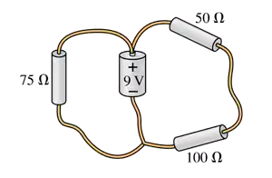
Draw a circuit diagram for the circuit of FIGURE EX28.2.
Circuit diagram showing a 9V battery connected to three resistors: 75Ω, 50Ω, and 100Ω in a combination circuit.

Guida verificata passo dopo passo
1
Identify the components of the circuit described in FIGURE EX28.2, such as resistors, capacitors, inductors, voltage sources, or current sources. Note their arrangement and connections.
Determine the type of circuit (e.g., series, parallel, or a combination) based on the description or visual representation provided in FIGURE EX28.2.
Use standard circuit symbols to represent each component. For example, use a zigzag line for resistors, a pair of parallel lines for capacitors, and a coil for inductors.
Arrange the components in the diagram according to their connections in the circuit. Ensure that all nodes and branches are accurately represented, and label each component with its value or identifier if provided.
Double-check the diagram for accuracy, ensuring that it matches the configuration described in FIGURE EX28.2 and adheres to standard circuit diagram conventions.

Risposta video verificata per un problema simile:

Questa soluzione video è stata consigliata dai nostri tutor come utile per risolvere questo problema.
Durata del video:
2m

Concetti chiave

Ecco i concetti essenziali che devi comprendere per rispondere correttamente alla domanda.

Circuit Diagram

A circuit diagram is a graphical representation of an electrical circuit, showing the components and their connections. It uses standardized symbols to represent elements like resistors, capacitors, and power sources, allowing for easy understanding and analysis of the circuit's function. Accurate circuit diagrams are essential for troubleshooting and constructing electrical systems.
Video consigliato:
Percorso guidato
08:07
Work and PV Diagrams

Components of a Circuit

Electrical circuits consist of various components, including power sources (like batteries), conductors (wires), and loads (like resistors or bulbs). Each component has a specific role; for example, power sources provide energy, while loads consume it. Understanding these components and their functions is crucial for drawing and analyzing circuit diagrams.
Video consigliato:
Percorso guidato
07:30
Vector Addition By Components

Ohm's Law

Ohm's Law is a fundamental principle in electronics that relates voltage (V), current (I), and resistance (R) in a circuit, expressed as V = IR. This law helps in calculating the behavior of electrical circuits, allowing one to determine how much current will flow through a circuit given a certain voltage and resistance. Mastery of Ohm's Law is essential for analyzing and designing circuits.
Video consigliato:
Percorso guidato
03:07
Resistance and Ohm's Law