Ch 30: Electromagnetic Induction
Knight Calc - Physics for Scientists and Engineers 5th Edition
Knight Calc5th EditionPhysics for Scientists and EngineersISBN: 9780137344796Non è quello che usi tu?Cambia libro di testo
Capitolo 30, Problema 77a

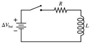
The switch in FIGURE P30.77 has been open for a long time. It is closed at t = 0 s. After the switch has been closed for a long time, what is the current in the circuit? Call this current I0.

Guida verificata passo dopo passo
1
Step 1: Analyze the circuit diagram. The circuit consists of a battery with voltage ΔV_bat, a resistor R, and an inductor L connected in series. The switch has been open for a long time, meaning no current was flowing initially, and the inductor had no stored energy.
Step 2: Understand the behavior of the inductor. When the switch is closed at t = 0 s, the inductor initially opposes the change in current due to its inductance. Over time, the current increases and the inductor's opposition diminishes as it reaches a steady state.
Step 3: At steady state (after the switch has been closed for a long time), the inductor behaves like a short circuit because the rate of change of current (dI/dt) becomes zero. This means the inductor no longer opposes the current flow.
Step 4: Apply Ohm's Law to the circuit at steady state. Since the inductor acts as a short circuit, the total resistance in the circuit is just R. The current I_0 can be calculated using the formula: I0=ΔVbatR.
Step 5: Conclude that the steady-state current I_0 depends only on the battery voltage ΔV_bat and the resistance R. To find the numerical value of I_0, substitute the given values of ΔV_bat and R into the formula.

Risposta video verificata per un problema simile:

Questa soluzione video è stata consigliata dai nostri tutor come utile per risolvere questo problema.

Concetti chiave

Ecco i concetti essenziali che devi comprendere per rispondere correttamente alla domanda.

Inductance

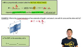
Inductance is a property of an electrical circuit that opposes changes in current. It is primarily associated with coils or loops of wire, where a changing current generates a magnetic field that induces an electromotive force (EMF) in the opposite direction. This phenomenon is crucial in understanding how circuits behave when switches are closed or opened, particularly in circuits containing inductors.
Video consigliato:
Percorso guidato
12:59
Mutual Induction

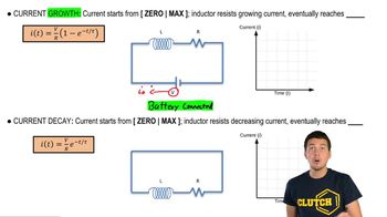
Steady State in RL Circuits

In an RL circuit, the steady state refers to the condition after the circuit has been closed for a long time, where the current reaches a constant value. At this point, the inductor behaves like a short circuit, and the entire voltage from the battery is dropped across the resistor. Understanding this concept is essential for determining the final current in the circuit after the switch is closed.
Video consigliato:

Ohm's Law

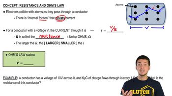
Ohm's Law states that the current (I) through a conductor between two points is directly proportional to the voltage (V) across the two points and inversely proportional to the resistance (R) of the conductor. Mathematically, it is expressed as V = IR. This law is fundamental in analyzing circuits, as it allows for the calculation of current when the voltage and resistance are known, particularly in the context of the steady state in RL circuits.
Video consigliato:
Percorso guidato
03:07
Resistance and Ohm's Law
Pratica correlata