Ch 32: AC Circuits
Knight Calc - Physics for Scientists and Engineers 5th Edition
Knight Calc5th EditionPhysics for Scientists and EngineersISBN: 9780137344796Non è quello che usi tu?Cambia libro di testo
Capitolo 32, Problema 55a

A series RLC circuit consists of a 50 Ω resistor, a 3.3 mH inductor, and a 480 nF capacitor. It is connected to a 5.0 kHz oscillator with a peak voltage of 5.0 V. What is the instantaneous current i when ε = ε0?

Guida verificata passo dopo passo
1
Step 1: Understand the problem. The goal is to find the instantaneous current i in a series RLC circuit when the voltage ε equals its peak value ε₀. This involves calculating the impedance Z of the circuit and using Ohm's law to determine the current.
Step 2: Calculate the angular frequency ω of the oscillator. The angular frequency is given by ω = 2πf, where f is the frequency of the oscillator. Substitute f = 5.0 kHz into the formula to find ω.
Step 3: Determine the reactance of the inductor (X_L) and the capacitor (X_C). The inductive reactance is given by X_L = ωL, where L is the inductance of the inductor. The capacitive reactance is given by X_C = 1 / (ωC), where C is the capacitance of the capacitor. Use the values of L = 3.3 mH and C = 480 nF to calculate X_L and X_C.
Step 4: Calculate the total impedance Z of the circuit. The impedance in a series RLC circuit is given by Z = √(R² + (X_L - X_C)²), where R is the resistance. Substitute the values of R, X_L, and X_C into the formula to find Z.
Step 5: Use Ohm's law to find the peak current I₀. Ohm's law states that I₀ = ε₀ / Z, where ε₀ is the peak voltage. Substitute ε₀ = 5.0 V and the calculated Z into the formula to find I₀. Since ε = ε₀, the instantaneous current i is equal to the peak current I₀.

Risposta video verificata per un problema simile:

Questa soluzione video è stata consigliata dai nostri tutor come utile per risolvere questo problema.

Concetti chiave

Ecco i concetti essenziali che devi comprendere per rispondere correttamente alla domanda.

RLC Circuit

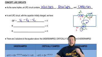
An RLC circuit is an electrical circuit consisting of a resistor (R), inductor (L), and capacitor (C) connected in series or parallel. The behavior of the circuit is influenced by the values of these components, which determine the circuit's impedance and resonance frequency. In this case, the series RLC circuit will respond to an alternating current (AC) source, such as the 5.0 kHz oscillator mentioned.
Video consigliato:

Impedance

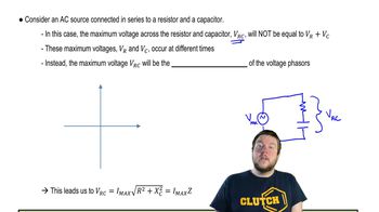
Impedance is the total opposition that a circuit offers to the flow of alternating current, combining resistance (R) and reactance (X). In an RLC circuit, the impedance can be calculated using the formula Z = √(R² + (X_L - X_C)²), where X_L is the inductive reactance and X_C is the capacitive reactance. Understanding impedance is crucial for determining the current in the circuit when a voltage is applied.
Video consigliato:
Percorso guidato
08:40
Impedance in AC Circuits

Instantaneous Current

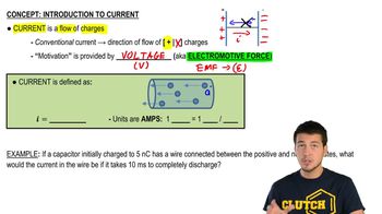
Instantaneous current refers to the current flowing through a circuit at a specific moment in time. In an AC circuit, this current varies sinusoidally with time, and its maximum value occurs when the voltage is at its peak. To find the instantaneous current when ε = ε₀, one must consider the phase relationship between voltage and current, which is influenced by the circuit's impedance.
Video consigliato:
Percorso guidato
05:38
Intro to Current