Ch 32: AC Circuits
Knight Calc - Physics for Scientists and Engineers 5th Edition
Knight Calc5th EditionPhysics for Scientists and EngineersISBN: 9780137344796Non è quello che usi tu?Cambia libro di testo
Capitolo 32, Problema 51b

A series RLC circuit consists of a 75 Ω resistor, a 0.12 H inductor, and a 30 μF capacitor. It is attached to a 120 V/60 Hz power line. What is the phase angle ϕ?

Guida verificata passo dopo passo
1
Determine the angular frequency (ω) of the AC source using the formula ω = 2πf, where f is the frequency of the power line (60 Hz).
Calculate the inductive reactance (X_L) using the formula X_L = ωL, where L is the inductance of the inductor (0.12 H).
Calculate the capacitive reactance (X_C) using the formula X_C = 1 / (ωC), where C is the capacitance of the capacitor (30 μF or 30 × 10⁻⁶ F).
Find the net reactance (X) of the circuit by subtracting the capacitive reactance from the inductive reactance: X = X_L - X_C.
Calculate the phase angle (ϕ) using the formula tan(ϕ) = X / R, where R is the resistance (75 Ω). Then, take the arctangent of the result to find ϕ in radians or degrees, depending on the desired unit.

Risposta video verificata per un problema simile:

Questa soluzione video è stata consigliata dai nostri tutor come utile per risolvere questo problema.

Concetti chiave

Ecco i concetti essenziali che devi comprendere per rispondere correttamente alla domanda.

Impedance in RLC Circuits

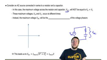
Impedance is the total opposition that a circuit offers to the flow of alternating current (AC) and is represented as a complex number. In a series RLC circuit, the impedance (Z) combines the resistance (R), inductive reactance (XL), and capacitive reactance (XC). The formula for impedance is Z = √(R² + (XL - XC)²), where XL = 2πfL and XC = 1/(2πfC), with f being the frequency.
Video consigliato:
Percorso guidato
08:40
Impedance in AC Circuits

Phase Angle in AC Circuits

The phase angle (ϕ) in an AC circuit indicates the phase difference between the voltage and the current. It is calculated using the formula ϕ = arctan((XL - XC) / R). A positive phase angle indicates that the circuit is inductive, while a negative angle indicates a capacitive circuit. The phase angle is crucial for understanding power factor and energy consumption in AC systems.
Video consigliato:
Percorso guidato
07:14
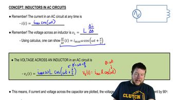
Inductors in AC Circuits

Resonance in RLC Circuits

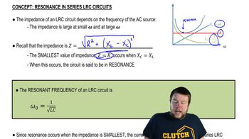
Resonance occurs in RLC circuits when the inductive reactance equals the capacitive reactance (XL = XC), resulting in maximum current flow and minimal impedance. At resonance, the phase angle is zero, meaning the voltage and current are in phase. Understanding resonance is important for analyzing circuit behavior at different frequencies and optimizing performance in AC applications.
Video consigliato:
Percorso guidato
05:23
Resonance in Series LRC Circuits