Ch 32: AC Circuits
Knight Calc - Physics for Scientists and Engineers 5th Edition
Knight Calc5th EditionPhysics for Scientists and EngineersISBN: 9780137344796Non è quello che usi tu?Cambia libro di testo
Capitolo 32, Problema 32b

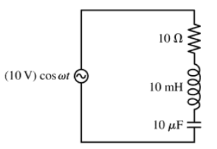
For the circuit of FIGURE EX32.32, Find VR and VL at resonance.

Guida verificata passo dopo passo
1
Step 1: Identify the components in the circuit. The circuit consists of a resistor (R = 10 Ω), an inductor (L = 10 mH), and a capacitor (C = 10 μF) connected in series with an AC voltage source of amplitude 10 V and frequency ω.
Step 2: Understand resonance in an RLC circuit. At resonance, the inductive reactance (XL) and capacitive reactance (XC) are equal, causing their effects to cancel each other out. The impedance of the circuit is purely resistive, equal to R.
Step 3: Calculate the resonance angular frequency (ω₀). The resonance condition is given by ω₀ = 1 / √(LC). Substitute L = 10 mH and C = 10 μF into the formula to find ω₀.
Step 4: Determine the voltage across the resistor (VR) at resonance. At resonance, the total voltage of the source is dropped across the resistor. Use Ohm's Law: VR = I × R, where I is the current. The current can be calculated as I = V / R, where V is the source voltage.
Step 5: Determine the voltage across the inductor (VL) at resonance. Even though the inductive reactance cancels the capacitive reactance, the voltage across the inductor can be calculated using VL = I × XL, where XL = ω₀ × L. Substitute the values of I, ω₀, and L to find VL.

Risposta video verificata per un problema simile:

Questa soluzione video è stata consigliata dai nostri tutor come utile per risolvere questo problema.

Concetti chiave

Ecco i concetti essenziali che devi comprendere per rispondere correttamente alla domanda.

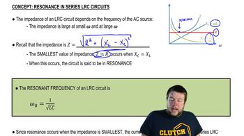
Resonance in RLC Circuits

Resonance occurs in RLC circuits when the inductive reactance (XL) equals the capacitive reactance (XC). At this point, the circuit can oscillate at its natural frequency, maximizing the current flow. The resonance frequency can be calculated using the formula f0 = 1/(2π√(LC)), where L is the inductance and C is the capacitance.
Video consigliato:
Percorso guidato
05:23
Resonance in Series LRC Circuits

Voltage Across Components

In an RLC circuit, the voltage across each component (resistor, inductor, and capacitor) can be determined using Ohm's law and the impedance of the circuit. At resonance, the total impedance is minimized, and the voltage across the resistor (VR) can be calculated using the current through the circuit and the resistance value.
Video consigliato:
Percorso guidato
07:14
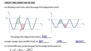
RMS Current and Voltage

Impedance in AC Circuits

Impedance (Z) in AC circuits is the total opposition to current flow, combining resistance (R) and reactance (X). It is expressed as Z = R + j(XL - XC), where j is the imaginary unit. At resonance, the impedance is purely resistive, simplifying calculations for voltages across the components.
Video consigliato:
Percorso guidato
08:40
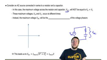
Impedance in AC Circuits