Ch. 40 - Molecules and Solids
Giancoli Douglas - Physics for Scientists and Engineers 5th edition
Giancoli Douglas5th editionPhysics for Scientists and EngineersISBN: 9780137488179당신이 사용하는 게 아니라요?교과서 변경
37장, 문제 87

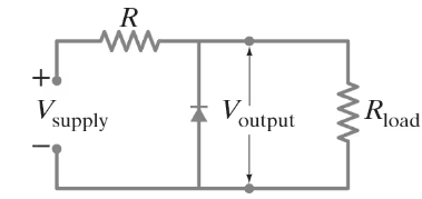
A zener diode voltage regulator is shown in Fig. 40–55. Suppose that R = 2.80 kΩ and that the diode breaks down at a reverse voltage of 130 V. (The current increases rapidly at this point, as shown on the far left of Fig. 40–38 at a voltage of -12V on that diagram.) The diode is rated at a maximum current of 120 mA. (a) If Rload = 21.0 kΩ, over what range of supply voltages will the circuit maintain the output voltage at 130 V? (b) If the supply voltage is 275 V, over what range of load resistance will the voltage be regulated?

검증된 단계별 안내
1
Step 1: Understand the problem. The zener diode voltage regulator is designed to maintain a constant output voltage of 130 V across the load resistor (Rload). The circuit's behavior depends on the supply voltage (Vs), the series resistor (R), and the load resistance (Rload). The diode's breakdown voltage is 130 V, and its maximum current is 120 mA. We need to analyze two scenarios: (a) the range of supply voltages for a given Rload, and (b) the range of load resistances for a given supply voltage.
Step 2: For part (a), calculate the range of supply voltages. The zener diode regulates the voltage when it is in breakdown mode. The current through the series resistor (R) is given by I = (Vs - Vz) / R, where Vz is the zener voltage (130 V). The current through the zener diode (Iz) is the difference between the current through R and the current through the load resistor (Iload). Use the formula Iload = Vz / Rload. To find the range of Vs, consider the two extreme cases: (1) when Iz = 0 (minimum Vs), and (2) when Iz = 120 mA (maximum Vs).
Step 3: For part (b), calculate the range of load resistances. When the supply voltage is fixed at 275 V, the current through the series resistor is I = (Vs - Vz) / R. The current through the zener diode is Iz = I - Iload. To maintain regulation, the zener diode must remain in breakdown mode, meaning Iz must be between 0 and 120 mA. Use the formula Iload = Vz / Rload to express the load resistance in terms of the current. Solve for the range of Rload by considering the two extreme cases: (1) when Iz = 0 (maximum Rload), and (2) when Iz = 120 mA (minimum Rload).
Step 4: Write the equations for each case. For part (a), the minimum supply voltage occurs when Iz = 0, so Vs_min = Vz + (Iload * R). The maximum supply voltage occurs when Iz = 120 mA, so Vs_max = Vz + ((Iload + Iz) * R). For part (b), the maximum load resistance occurs when Iz = 0, so Rload_max = Vz / Iload. The minimum load resistance occurs when Iz = 120 mA, so Rload_min = Vz / (Iload + Iz).
Step 5: Substitute the given values into the equations. Use R = 2.80 kΩ, Vz = 130 V, Rload = 21.0 kΩ, Vs = 275 V, and Iz_max = 120 mA. Perform the calculations to determine the range of supply voltages for part (a) and the range of load resistances for part (b). Ensure that the units are consistent throughout the calculations.

비슷한 문제에 대한 검증된 영상 답변:

이 영상 해법은 위 문제에 도움이 된다고 튜터들이 추천한 것입니다.
영상 길이:
7m
도움이 되었나요?

주요 개념

질문에 올바르게 답하기 위해 반드시 이해해야 하는 핵심 개념들은 다음과 같습니다.

Zener Diode Operation

A Zener diode is designed to allow current to flow in the reverse direction when a specific breakdown voltage is reached, known as the Zener voltage. In this case, the diode breaks down at 130 V, maintaining a stable output voltage across the load. This property is crucial for voltage regulation in circuits, as it ensures that the output voltage remains constant despite variations in supply voltage or load conditions.
추천 영상:
가이드 코스
08:22
Operations with Significant Figures

Voltage Regulation

Voltage regulation refers to the ability of a circuit to maintain a constant output voltage despite changes in input voltage or load current. In the context of the Zener diode regulator, the output voltage remains at 130 V as long as the supply voltage is above a certain threshold and the load current does not exceed the diode's maximum rating. Understanding the conditions under which voltage regulation occurs is essential for analyzing the circuit's performance.
추천 영상:
가이드 코스
07:14
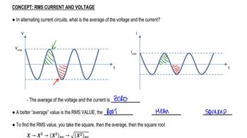
RMS Current and Voltage

Ohm's Law and Load Resistance

Ohm's Law states that the current through a conductor between two points is directly proportional to the voltage across the two points and inversely proportional to the resistance. In this scenario, the load resistance (Rload) affects the current drawn from the Zener diode and, consequently, the voltage regulation. By calculating the current through the load and the Zener diode, one can determine the range of load resistances that will allow the circuit to maintain the desired output voltage.
추천 영상:
가이드 코스
03:07
Resistance and Ohm's Law