
Ch 30: Electromagnetic Induction
Knight Calc - Physics for Scientists and Engineers 5th Edition
Knight Calc5th EditionPhysics for Scientists and EngineersISBN: 9780137344796당신이 사용하는 게 아니라요?교과서 변경
30장, 문제 49

CALC An electric generator has an 18-cm-diameter, 120-turn coil that rotates at 60 Hz in a uniform magnetic field that is perpendicular to the rotation axis. What magnetic field strength is needed to generate a peak voltage of 170 V?

검증된 단계별 안내
1
Understand the problem: The generator produces an alternating voltage due to the rotation of the coil in a magnetic field. The peak voltage (emf) is given by the formula: Vpeak=NABω, where N is the number of turns, A is the area of the coil, B is the magnetic field strength, and ω is the angular velocity. We need to solve for B.
Calculate the area of the coil: The coil is circular with a diameter of 18 cm. The radius is half the diameter, so r=18/2=9 cm or 0.09 m. The area of the coil is given by A=πr^2=π(0.09)^2.
Determine the angular velocity: The coil rotates at a frequency of 60 Hz. The angular velocity is related to the frequency by the formula ω=2πf, where f is the frequency. Substitute f=60 Hz to find ω.
Rearrange the peak voltage formula to solve for B: Using Vpeak=NABω, isolate B to get B=Vpeak/(NAω). Substitute the known values: Vpeak=170 V, N=120, A (calculated in step 2), and ω (calculated in step 3).
Perform the substitution and simplify the expression to find the magnetic field strength B. Ensure all units are consistent (e.g., meters for area, radians per second for angular velocity) before calculating.

비슷한 문제에 대한 검증된 영상 답변:

이 영상 해법은 위 문제에 도움이 된다고 튜터들이 추천한 것입니다.
도움이 되었나요?

주요 개념

질문에 올바르게 답하기 위해 반드시 이해해야 하는 핵심 개념들은 다음과 같습니다.

Faraday's Law of Electromagnetic Induction

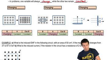
Faraday's Law states that a change in magnetic flux through a coil induces an electromotive force (EMF) in the coil. The induced voltage is proportional to the rate of change of the magnetic flux and the number of turns in the coil. This principle is fundamental in understanding how generators convert mechanical energy into electrical energy.
추천 영상:

Magnetic Flux

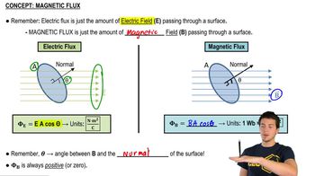
Magnetic flux is defined as the product of the magnetic field strength and the area through which the field lines pass, taking into account the angle between the field lines and the normal to the surface. It is measured in Weber (Wb) and is crucial for calculating the induced voltage in a coil as it directly relates to the amount of magnetic field interacting with the coil.
추천 영상:

Peak Voltage in AC Generators

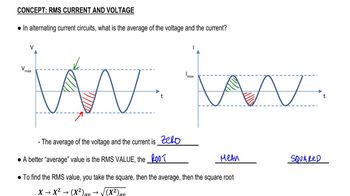
In alternating current (AC) generators, the peak voltage is the maximum voltage produced during one cycle of rotation. It can be calculated using the formula V_peak = N * A * B * ω, where N is the number of turns, A is the area of the coil, B is the magnetic field strength, and ω is the angular frequency. Understanding this relationship is essential for determining the required magnetic field strength to achieve a specific peak voltage.
추천 영상:
가이드 코스
07:14
RMS Current and Voltage
관련 실천
교과서 질문

A 2.0 cm×2.0 cm square loop of wire with resistance 0.010 Ω has one edge parallel to a long straight wire. The near edge of the loop is 1.0 cm from the wire. The current in the wire is increasing at the rate of 100 A/s. What is the current in the loop?

153
views
교과서 질문

A small, 2.0-mm-diameter circular loop with R = 0.020 Ω is at the center of a large 100-mm-diameter circular loop. Both loops lie in the same plane. The current in the outer loop changes from +1.0 A to −1.0 A in 0.10 s. What is the induced current in the inner loop?

69
views
교과서 질문

FIGURE P30.48 shows two 20-turn coils tightly wrapped on the same 2.0-cm-diameter cylinder with 1.0-mm-diameter wire. The current through coil 1 is shown in the graph. Determine the current in coil 2 at (a) t = 0.05 s and (b) t = 0.25 s. A positive current is into the figure at the top of a loop. Assume that the magnetic field of coil 1 passes entirely through coil 2.

1771
views
교과서 질문

FIGURE P30.47 shows a 1.0-cm-diameter loop with R = 0.50 Ω inside a 2.0-cm-diameter solenoid. The solenoid is 8.0 cm long, has 120 turns, and carries the current shown in the graph. A positive current is cw when seen from the left. Determine the current in the loop at t = 0.010 s.

145
views
교과서 질문

CALC The L-shaped conductor in FIGURE P30.54 moves at 10 m/s across and touches a stationary L-shaped conductor in a 0.10 T magnetic field. The two vertices overlap, so that the enclosed area is zero, at t = 0 s. The conductor has a resistance of 0.010 ohms per meter. a. What is the direction of the induced current?

1402
views
교과서 질문

A rectangular metal loop with 0.050 Ω resistance is placed next to one wire of the RC circuit shown in FIGURE P30.53. The capacitor is charged to 20 V with the polarity shown, then the switch is closed at t = 0 s. What is the current in the loop at t = 5.0 μs? Assume that only the circuit wire next to the loop is close enough to produce a significant magnetic field.

124
views