Ch 30: Electromagnetic Induction
Knight Calc - Physics for Scientists and Engineers 5th Edition
Knight Calc5th EditionPhysics for Scientists and EngineersISBN: 9780137344796당신이 사용하는 게 아니라요?교과서 변경
30장, 문제 75a

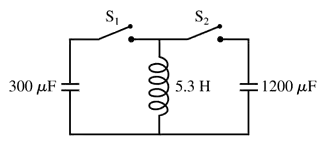
The 300 μF capacitor in FIGURE P30.75 is initially charged to 100 V, the 1200 μF capacitor is uncharged, and the switches are both open. What is the maximum voltage to which you can charge the 1200 μF capacitor by the proper closing and opening of the two switches?
Circuit diagram showing a 300 μF capacitor, a 1200 μF capacitor, and a 5.3 H inductor with two open switches.

검증된 단계별 안내
1
Identify the key components of the circuit: a 300 μF capacitor initially charged to 100 V, a 1200 μF capacitor initially uncharged, and two switches. The goal is to determine the maximum voltage that can be achieved on the 1200 μF capacitor by appropriately operating the switches.
Understand the principle of charge conservation: When capacitors are connected in parallel (via the switches), the total charge is conserved, and the voltage across both capacitors becomes the same. The total charge before connection is distributed between the two capacitors after connection.
Calculate the initial charge on the 300 μF capacitor using the formula for charge: Q = C × V. Here, C = 300 μF and V = 100 V. This gives the initial charge on the 300 μF capacitor.
When the switches are closed to connect the two capacitors in parallel, the total charge (Q_total) is shared between the 300 μF and 1200 μF capacitors. Use the formula for the final voltage across both capacitors: V_final = Q_total / (C1 + C2), where C1 = 300 μF and C2 = 1200 μF.
To maximize the voltage on the 1200 μF capacitor, ensure that the 300 μF capacitor is fully discharged into the 1200 μF capacitor by opening the switches at the appropriate time. The maximum voltage on the 1200 μF capacitor will be equal to the final voltage calculated in the previous step.

비슷한 문제에 대한 검증된 영상 답변:

이 영상 해법은 위 문제에 도움이 된다고 튜터들이 추천한 것입니다.
영상 길이:
6m

주요 개념

질문에 올바르게 답하기 위해 반드시 이해해야 하는 핵심 개념들은 다음과 같습니다.

Capacitance

Capacitance is the ability of a capacitor to store electrical charge per unit voltage. It is measured in farads (F) and is defined as the ratio of the charge (Q) stored on one plate of the capacitor to the voltage (V) across the plates, expressed as C = Q/V. In this problem, understanding the capacitance values of the capacitors involved is crucial for calculating the charge transfer and resulting voltage.
추천 영상:
가이드 코스
08:02
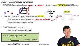
Capacitors & Capacitance (Intro)

Charge Conservation

Charge conservation is a fundamental principle stating that the total electric charge in an isolated system remains constant. When capacitors are connected in a circuit, the charge can redistribute between them, but the total charge before and after any switching action must remain the same. This principle is essential for determining the maximum voltage that can be achieved on the 1200 μF capacitor after the switches are manipulated.
추천 영상:
가이드 코스
05:43
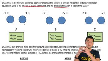
Conservation of Charge

Voltage Division

Voltage division is a technique used in circuits to determine the voltage across components in series. When capacitors are connected in series, the total voltage across the series is divided among the capacitors based on their capacitance values. This concept is important for calculating the final voltage across the 1200 μF capacitor after the charge from the 300 μF capacitor is transferred, as it helps predict how the voltage will be shared.
추천 영상:
가이드 코스
07:14
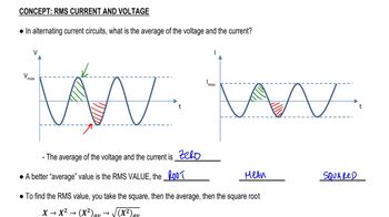
RMS Current and Voltage