Ch 32: AC Circuits
Knight Calc - Physics for Scientists and Engineers 5th Edition
Knight Calc5th EditionPhysics for Scientists and EngineersISBN: 9780137344796당신이 사용하는 게 아니라요?교과서 변경
32장, 문제 64

A generator consists of a 12-cm by 16-cm rectangular loop with 500 turns of wire spinning at 60 Hz in a 25 mT uniform magnetic field. The generator output is connected to a series RC circuit consisting of a 120 Ω resistor and a 35 μF capacitor. What is the average power delivered to the circuit?

검증된 단계별 안내
1
Calculate the area of the rectangular loop using the formula \( A = l \times w \), where \( l = 12 \ \text{cm} = 0.12 \ \text{m} \) and \( w = 16 \ \text{cm} = 0.16 \ \text{m} \).
Determine the maximum emf (electromotive force) generated by the loop using the formula \( \mathcal{E}_{\text{max}} = N \cdot B \cdot A \cdot \omega \), where \( N = 500 \) (number of turns), \( B = 25 \ \text{mT} = 0.025 \ \text{T} \), \( A \) is the area calculated in step 1, and \( \omega = 2 \pi f \) with \( f = 60 \ \text{Hz} \).
Find the root mean square (RMS) value of the emf using the relationship \( \mathcal{E}_{\text{rms}} = \frac{\mathcal{E}_{\text{max}}}{\sqrt{2}} \).
Calculate the total impedance of the RC circuit using the formula \( Z = \sqrt{R^2 + \left( \frac{1}{\omega C} \right)^2} \), where \( R = 120 \ \Omega \), \( \omega = 2 \pi f \), and \( C = 35 \ \mu\text{F} = 35 \times 10^{-6} \ \text{F} \).
Determine the average power delivered to the circuit using the formula \( P_{\text{avg}} = \frac{\mathcal{E}_{\text{rms}}^2}{Z} \).

비슷한 문제에 대한 검증된 영상 답변:

이 영상 해법은 위 문제에 도움이 된다고 튜터들이 추천한 것입니다.
영상 길이:
10m
도움이 되었나요?

주요 개념

질문에 올바르게 답하기 위해 반드시 이해해야 하는 핵심 개념들은 다음과 같습니다.

Electromagnetic Induction

Electromagnetic induction is the process by which a changing magnetic field within a closed loop induces an electromotive force (EMF) in the wire. This principle, described by Faraday's Law, states that the induced EMF is proportional to the rate of change of magnetic flux through the loop. In this question, the spinning loop in a magnetic field generates an alternating current due to its motion.
추천 영상:
05:42
Introduction to Induction

AC Circuit Analysis

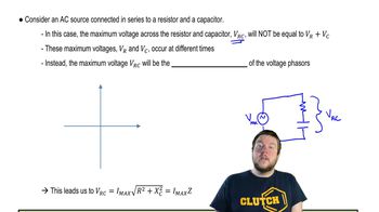
AC circuit analysis involves understanding how alternating current (AC) behaves in circuits, particularly with components like resistors and capacitors. The impedance in an RC circuit combines resistance and reactance, affecting the current and voltage relationship. The average power delivered to the circuit can be calculated using the root mean square (RMS) values of voltage and current, along with the phase angle between them.
추천 영상:
08:40
Impedance in AC Circuits

Power in AC Circuits

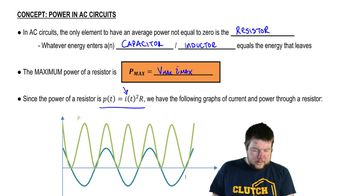
In AC circuits, the average power delivered is calculated using the formula P = VIcos(φ), where V is the RMS voltage, I is the RMS current, and φ is the phase angle between the voltage and current. The presence of reactive components like capacitors can cause the current to lag or lead the voltage, affecting the power factor. Understanding this concept is crucial for determining how much power is effectively used in the circuit.
추천 영상:
05:37
Power in AC Circuits
관련 실천
교과서 질문

A television channel is assigned the frequency range from 54 MHz to 60 MHz. A series RLC tuning circuit in a TV receiver resonates in the middle of this frequency range. The circuit uses a 16 pF capacitor. What is the value of the inductor?

1860
views
교과서 질문

A motor attached to a 120 V/60 Hz power line draws an 8.0 A current. Its average energy dissipation is 800 W. What is the rms resistor voltage?

158
views
교과서 질문

Commercial electricity is generated and transmitted as three-phase electricity. Instead of a single emf ε = ε0 cos ωt, three separate wires carry currents for the emfs ε1 = ε0 cos ωt, ε2 = ε0 cos(ωt+120°), and ε3 = ε0 cos(ωt−120°). This is why the long-distance transmission lines you see in the countryside have three parallel wires, as do many distribution lines within a city. Show that the potential difference between any two of the phases has the rms value 3–√ εrms, where εrms is the familiar single-phase rms voltage. Evaluate this potential difference for εrms = 120 V. Some high-power home appliances, especially electric clothes dryers and hot-water heaters, are designed to operate between two of the phases rather than between one phase and neutral. Heavy-duty industrial motors are designed to operate from all three phases, but full three-phase power is rare in residential or office use.

111
views
교과서 질문

Commercial electricity is generated and transmitted as three-phase electricity. Instead of a single emf, three separate wires carry currents for the emfs ε1 = ε0 cos ωt, ε2 = ε0 cos(ωt +120°), and ε3 = ε0 cos(ωt−120°) over three parallel wires, each of which supplies one-third of the power. This is why the long-distance transmission lines you see in the countryside have three wires. Suppose the transmission lines into a city supply a total of 450 MW of electric power, a realistic value. What would be the rms current in each wire if the transmission voltage were ε0 = 120 V rms?

1691
views
교과서 질문

You're the operator of a 15,000 V rms, 60 Hz electrical substation. When you get to work one day, you see that the station is delivering 6.0 MW of power with a power factor of 0.90. What is the rms current leaving the station?

144
views
교과서 질문

Commercial electricity is generated and transmitted as three-phase electricity. Instead of a single emf, three separate wires carry currents for the emfs ε1 = ε0 cos ωt, ε2 = ε0 cos(ωt +120°), and ε3 = ε0 cos(ωt−120°) over three parallel wires, each of which supplies one-third of the power. This is why the long-distance transmission lines you see in the countryside have three wires. Suppose the transmission lines into a city supply a total of 450 MW of electric power, a realistic value. In fact, transformers are used to step the transmission-line voltage up to 500 kV rms. What is the current in each wire?

1690
views