Ch 32: AC Circuits
Knight Calc - Physics for Scientists and Engineers 5th Edition
Knight Calc5th EditionPhysics for Scientists and EngineersISBN: 9780137344796당신이 사용하는 게 아니라요?교과서 변경
32장, 문제 60b

The tuning circuit in an FM radio receiver is a series RLC circuit with a 0.200 μH inductor. FM radio stations are assigned frequencies every 0.2 MHz, but two nearby stations cannot use adjacent frequencies. What is the maximum resistance the tuning circuit can have if the peak current at a frequency of 103.9 MHz, the closest frequency that can be used by a nearby station, is to be no more than 0.10% of the peak current at 104.3 MHz? The radio is still tuned to 104.3 MHz, and you can assume the two stations have equal strength.

검증된 단계별 안내
1
Step 1: Understand the problem. The tuning circuit is a series RLC circuit, and the goal is to determine the maximum resistance such that the peak current at 103.9 MHz is no more than 0.10% of the peak current at 104.3 MHz. This involves analyzing the frequency response of the circuit and the relationship between current and impedance.
Step 2: Write the formula for the impedance of a series RLC circuit. The impedance \( Z \) is given by: \( Z = \sqrt{R^2 + \left( \omega L - \frac{1}{\omega C} \right)^2} \), where \( \omega = 2 \pi f \) is the angular frequency, \( L \) is the inductance, \( C \) is the capacitance, and \( R \) is the resistance.
Step 3: Relate the current to the impedance. The peak current \( I \) is inversely proportional to the impedance: \( I = \frac{V}{Z} \), where \( V \) is the peak voltage. Since the problem specifies the ratio of currents at two frequencies, you can use the ratio of impedances to find the maximum resistance.
Step 4: Calculate the angular frequencies for 104.3 MHz and 103.9 MHz. Use \( \omega = 2 \pi f \), where \( f \) is the frequency in Hz. Convert MHz to Hz by multiplying by \( 10^6 \). For example, \( \omega_{104.3} = 2 \pi \times 104.3 \times 10^6 \). Perform similar calculations for \( \omega_{103.9} \).
Step 5: Set up the ratio of currents and solve for \( R \). The problem states that \( I_{103.9} \leq 0.001 \times I_{104.3} \). Substitute \( I = \frac{V}{Z} \) into this inequality, and express \( Z \) in terms of \( R \), \( L \), \( C \), and \( \omega \). Solve the inequality for \( R \), ensuring that the resistance satisfies the condition for the given frequencies.

비슷한 문제에 대한 검증된 영상 답변:

이 영상 해법은 위 문제에 도움이 된다고 튜터들이 추천한 것입니다.
영상 길이:
15m

주요 개념

질문에 올바르게 답하기 위해 반드시 이해해야 하는 핵심 개념들은 다음과 같습니다.

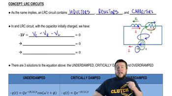
RLC Circuit

An RLC circuit consists of a resistor (R), inductor (L), and capacitor (C) connected in series or parallel. It is fundamental in understanding how circuits can resonate at specific frequencies, which is crucial for tuning in radio frequencies. The behavior of the circuit is characterized by its impedance, which varies with frequency, affecting the current and voltage across each component.
추천 영상:

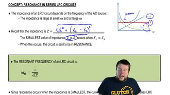
Resonance Frequency

The resonance frequency of an RLC circuit is the frequency at which the inductive and capacitive reactances are equal in magnitude, resulting in maximum current flow. This frequency is determined by the values of the inductor and capacitor in the circuit. For FM radio, tuning to the resonance frequency allows the circuit to effectively select a specific station while minimizing interference from others.
추천 영상:
가이드 코스
05:23
Resonance in Series LRC Circuits

Quality Factor (Q)

The quality factor (Q) of an RLC circuit measures its selectivity and bandwidth. A higher Q indicates a narrower bandwidth and better selectivity, meaning the circuit can distinguish between closely spaced frequencies. In the context of the FM radio question, the Q factor is essential for determining the maximum resistance allowable in the circuit to maintain the desired peak current at the tuned frequency while avoiding interference from nearby stations.
추천 영상:
가이드 코스
04:32
Dielectric Breakdown
관련 실천
교과서 질문

A television channel is assigned the frequency range from 54 MHz to 60 MHz. A series RLC tuning circuit in a TV receiver resonates in the middle of this frequency range. The circuit uses a 16 pF capacitor. What is the value of the inductor?

1860
views
교과서 질문

The tuning circuit in an FM radio receiver is a series RLC circuit with a 0.200 μH inductor. The receiver is tuned to a station at 104.3 MHz. What is the value of the capacitor in the tuning circuit?

136
views
교과서 질문

Commercial electricity is generated and transmitted as three-phase electricity. Instead of a single emf, three separate wires carry currents for the emfs ε1 = ε0 cos ωt, ε2 = ε0 cos(ωt +120°), and ε3 = ε0 cos(ωt−120°) over three parallel wires, each of which supplies one-third of the power. This is why the long-distance transmission lines you see in the countryside have three wires. Suppose the transmission lines into a city supply a total of 450 MW of electric power, a realistic value. What would be the rms current in each wire if the transmission voltage were ε0 = 120 V rms?

1691
views
교과서 질문

A series RLC circuit consists of a 50 Ω resistor, a 3.3 mH inductor, and a 480 nF capacitor. It is connected to a 5.0 kHz oscillator with a peak voltage of 5.0 V. What is the instantaneous current i when ε = ε0?

231
views
교과서 질문

Commercial electricity is generated and transmitted as three-phase electricity. Instead of a single emf, three separate wires carry currents for the emfs ε1 = ε0 cos ωt, ε2 = ε0 cos(ωt +120°), and ε3 = ε0 cos(ωt−120°) over three parallel wires, each of which supplies one-third of the power. This is why the long-distance transmission lines you see in the countryside have three wires. Suppose the transmission lines into a city supply a total of 450 MW of electric power, a realistic value. In fact, transformers are used to step the transmission-line voltage up to 500 kV rms. What is the current in each wire?

1690
views
교과서 질문

Show that the power factor of a series RLC circuit is cos ϕ=R/Z.

196
views