The peak current through an inductor is 10 mA. What is the peak current if the emf peak voltage is doubled (at the original frequency)?
Ch 32: AC Circuits
32장, 문제 19a
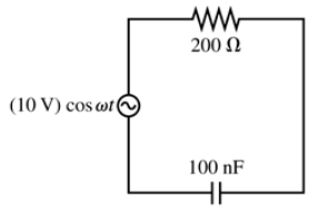
What are VR and VC if the emf frequency in FIGURE EX32.19 is 2.5 kHz?

검증된 단계별 안내1
Step 1: Identify the components in the circuit from FIGURE EX32.19. Typically, this involves a resistor (R), a capacitor (C), and an alternating current (AC) source with a given frequency. The problem asks for the voltage across the resistor (Vᵣ) and the capacitor (Vc).
Step 2: Recall the formulas for the impedance of the resistor and capacitor in an AC circuit. The impedance of the resistor is simply R, while the impedance of the capacitor is given by \( Z_c = \frac{1}{\omega C} \), where \( \omega = 2 \pi f \) is the angular frequency and \( f \) is the frequency of the AC source.
Step 3: Calculate the angular frequency \( \omega \) using \( \omega = 2 \pi f \). Substitute \( f = 2.5 \text{ kHz} \) into the formula to find \( \omega \).
Step 4: Use Ohm's Law and the concept of voltage division in AC circuits to find the voltages across the resistor and capacitor. The voltage across the resistor \( Vᵣ \) is given by \( Vᵣ = I R \), and the voltage across the capacitor \( V_c \) is given by \( V_c = I Z_c \), where \( I \) is the current in the circuit. The current can be determined using the total impedance of the circuit.
Step 5: Combine the results to express \( Vᵣ \) and \( V_c \) in terms of the given values (R, C, f, and the emf of the AC source). Ensure that the calculations are consistent with the circuit configuration provided in FIGURE EX32.19.

비슷한 문제에 대한 검증된 영상 답변:
이 영상 해법은 위 문제에 도움이 된다고 튜터들이 추천한 것입니다.
도움이 되었나요?
주요 개념
질문에 올바르게 답하기 위해 반드시 이해해야 하는 핵심 개념들은 다음과 같습니다.
Electromotive Force (emf)
Electromotive force (emf) is the voltage generated by a source such as a battery or generator when no current is flowing. It represents the energy per unit charge produced by the source and is crucial for understanding how electrical circuits operate. In the context of alternating current (AC) circuits, the emf can vary with frequency, affecting the behavior of circuit components.
추천 영상:
가이드 코스
Motional EMF
Resonant Frequency (Vᵣ)
Resonant frequency (Vᵣ) is the frequency at which a system naturally oscillates when not subjected to a continuous external force. In electrical circuits, this occurs when the inductive and capacitive reactances are equal, leading to maximum voltage and current at that frequency. Understanding resonant frequency is essential for analyzing circuits that include inductors and capacitors.
추천 영상:
가이드 코스
Resonance in Series LRC Circuits
Capacitive Voltage (Vc)
Capacitive voltage (Vc) refers to the voltage across a capacitor in an AC circuit. It is influenced by the frequency of the applied emf and the capacitance value. As frequency increases, the capacitive reactance decreases, allowing more current to flow through the capacitor, which in turn affects the overall voltage distribution in the circuit.
추천 영상:
가이드 코스
Capacitors & Capacitance (Intro)
관련 실천
교과서 질문
1176
views
교과서 질문
What are VR and VC if the emf frequency in FIGURE EX32.19 is 25 kHz?
103
views
교과서 질문
A high-pass RC filter is connected to an AC source with a peak voltage of 10.0 V. The peak capacitor voltage is 6.0 V. What is the peak resistor voltage?
137
views
교과서 질문
A low-pass filter consists of a 100 μF capacitor in series with a 159 Ω resistor. The circuit is driven by an AC source with a peak voltage of 5.00 V. What is the crossover frequency fc?
138
views
교과서 질문
A high-pass RC filter with a crossover frequency of 1000 Hz uses a 100 Ω resistor. What is the value of the capacitor?
121
views
교과서 질문
FIGURE EX32.24 shows voltage and current graphs for an inductor. What is the emf frequency f?
137
views