 Back
Electromagnetic Induction and Faraday’s Law: Study Notes
Study Guide - Smart Notes
 Tailored notes based on your materials, expanded with key definitions, examples, and context.
Electromagnetic Induction and Faraday’s Law
Magnetic Flux
Magnetic flux is a measure of the quantity of magnetism, taking into account the strength and the extent of a magnetic field. It is a fundamental concept in understanding electromagnetic induction.
Definition: Magnetic flux (\( \Phi \)) is given by the formula: where B is the magnetic field strength, A is the area perpendicular to the field, and \( \theta \) is the angle between the field and the area vector.
SI Unit: Weber (Wb), where 1 Wb = 1 T·m2.
Changing Magnetic Flux: Flux can be changed by altering the area (A), the angle (\( \theta \)), or the magnetic field (B).
Example: For a wire loop of radius 0.50 m in a 0.60 T field:
(a) Perpendicular (\( \theta = 0^\circ \)):
(b) Parallel (\( \theta = 90^\circ \)):
(c) At 30°:
Faraday’s Law of Induction
Faraday’s Law states that a changing magnetic flux through a loop induces an electromotive force (emf) in the loop.
Formula: where E is the induced emf, N is the number of turns, and \( \frac{d\Phi}{dt} \) is the rate of change of magnetic flux.
Lenz’s Law: The induced emf always acts to oppose the change in magnetic flux.
Example: A coil of 200 turns, area 0.18 m × 0.18 m, resistance 2.00 Ω, magnetic field changes from 0 to 0.500 T in 0.800 s at 35° to the plane. Find induced emf and current.
Lenz’s Law: Determining Direction of Induced Current
Lenz’s Law helps determine the direction of the induced current in a loop due to changing magnetic flux.
Steps:
Determine the direction of the external magnetic field (B).
Determine if the flux is increasing or decreasing.
Choose the current direction to create an induced magnetic field that opposes the change in flux.
Example: If the area of a loop decreases in a field pointing into the page, the induced current will be clockwise to increase the flux.
Motional emf
Motional emf is generated when a conductor moves through a magnetic field, causing a separation of charges and creating a potential difference.
Formula: where B is the magnetic field, L is the length of the conductor, and v is the velocity.
Force on Charges:
Force on Rod:
Example: Driving a car at 75 mph in Earth’s magnetic field induces an emf across the car’s width.
Eddy Currents
Eddy currents are loops of electrical current induced within conductors by a changing magnetic field. They can cause energy dissipation and magnetic braking.
Definition: Eddy currents flow in metal plates, tubes, etc., not just wires.
Effects: Cause heating and resist motion (magnetic braking).
Electric Generators and Motors
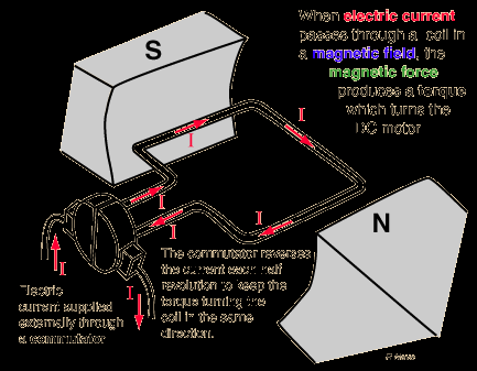
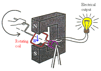
Electric generators convert mechanical energy to electrical energy, while motors convert electrical energy to mechanical energy. Both operate on principles of electromagnetic induction.
Generator: Rotating a coil in a magnetic field induces a current.
Motor: Running a current through a coil in a magnetic field produces torque and rotation.
Generator emf: where N is number of turns, A is area, B is field, \omega is angular velocity.
Countertorque: The induced current creates a torque opposing the motion.
Counter emf in Motors: When a motor spins, it acts as a generator, producing an emf that opposes the applied voltage.
Current in Motor: where V is applied voltage, E is counter emf, R is resistance.
Self and Mutual Inductance
Inductance is the property of a circuit that opposes changes in current due to electromagnetic induction.
Self Inductance: where L is inductance.
Mutual Inductance: where M is mutual inductance between two coils.
SI Unit: Henry (H).
Energy in an Inductor
Inductors store energy in their magnetic fields.
Energy Stored:
Energy Density:
Transformers
Transformers use electromagnetic induction to change the voltage and current in AC circuits. They consist of primary and secondary coils.
Voltage Ratio:
Current Ratio:
Power Conservation:
Works only with AC: Transformers require alternating current to operate.
Example: If the primary coil has 20 turns and the secondary coil receives 60 W at 0.10 A, calculate voltage and number of turns.
Capacitors and Inductors in AC Circuits
Capacitors and inductors behave differently in AC circuits compared to DC circuits, affecting current and voltage phase relationships.
Capacitive Reactance:
Inductive Reactance:
Frequency Dependence: Reactance changes with frequency; capacitors act as open circuits at low frequency, closed at high frequency, while inductors act as regular resistors at low frequency and increase resistance at high frequency.
Example: An 8.00 µF capacitor in a 150 V, 60 Hz AC circuit: calculate reactance and rms current; observe changes if frequency is doubled.
Summary Table: Key Formulas and Concepts
Concept | Formula | SI Unit |
|---|---|---|
Magnetic Flux | Weber (Wb) | |
Faraday’s Law | Volt (V) | |
Motional emf | Volt (V) | |
Self Inductance | Henry (H) | |
Energy in Inductor | Joule (J) | |
Capacitive Reactance | Ohm (Ω) | |
Inductive Reactance | Ohm (Ω) | |
Transformer Voltage Ratio | — |
Additional info: Academic context and examples were expanded for clarity and completeness. Images included are directly relevant to the explanation of electric motors and generators.
