 Back
BackAC Circuits: Inductors, Capacitors, and RLC Circuits
Study Guide - Smart Notes
 Tailored notes based on your materials, expanded with key definitions, examples, and context.
Inductors and Inductance
Introduction to Inductors
Inductors are passive circuit elements that store energy in their magnetic field when current flows through them. The property of an inductor to oppose changes in current is called inductance, denoted by L, and measured in henries (H).
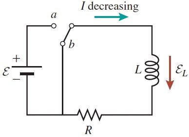
Induced emf (𝜀): When the current through an inductor changes, an emf is induced that opposes the change, according to Faraday's Law.
Energy Storage: The energy stored in an inductor is in the form of a magnetic field.

Analogy with Capacitors
Inductors and capacitors are analogous in their energy storage properties, but while capacitors store energy in electric fields, inductors store energy in magnetic fields.
Capacitor: Stores energy in an electric field between plates.
Inductor: Stores energy in a magnetic field inside the coil.
Inductance of a Solenoid
The inductance of a solenoid depends on its physical properties: number of turns, length, and cross-sectional area. For an ideal solenoid:
Formula:
Where is the number of turns per unit length, is the length, is the cross-sectional area, and is the permeability of free space.
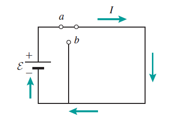
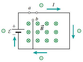
RL Circuits: Charging and Discharging
Current Growth and Decay in RL Circuits
When a switch is closed in an RL circuit, the current does not immediately reach its maximum value due to the inductor's opposition to change. The current increases exponentially with a time constant .
Charging (Current Increasing):
Discharging (Current Decreasing):
Energy in Inductors
Energy Stored in a Magnetic Field
The energy stored in an inductor is given by:
This energy is stored in the magnetic field created by the current in the inductor.
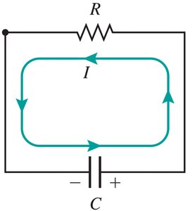
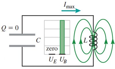
LC Circuits: Oscillations
Energy Exchange in LC Circuits
In an LC circuit, energy oscillates between the electric field of the capacitor and the magnetic field of the inductor. The total energy remains constant (in the absence of resistance).
Total Energy:
At different times, all energy may be in the capacitor, in the inductor, or shared between both.
AC Circuits: Fundamentals
Alternating Current (AC) and Voltage
AC circuits are powered by sources that produce sinusoidally varying voltages and currents. The instantaneous voltage is given by:
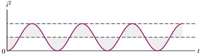
Root Mean Square (rms) Values: ,
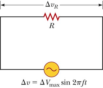
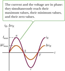
Power in AC Circuits
The average power dissipated in a resistor in an AC circuit is:
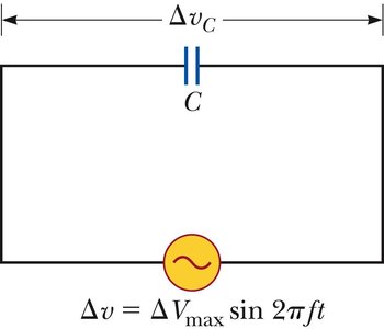
Capacitors and Inductors in AC Circuits
Capacitive Reactance
The opposition of a capacitor to AC is called capacitive reactance:
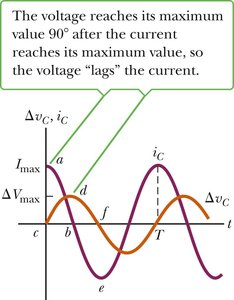
Voltage lags current by 90° in a capacitor.
Inductive Reactance
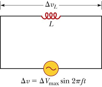
The opposition of an inductor to AC is called inductive reactance:
Voltage leads current by 90° in an inductor.
Series RLC Circuits
Impedance and Phase Relationships
When a resistor, inductor, and capacitor are connected in series to an AC source, the total opposition to current is called impedance (Z):
The phase angle between the current and voltage is given by
Phasor Diagrams
Phasor diagrams are used to represent the phase relationships between voltages across the resistor, inductor, and capacitor.
Resonance in RLC Circuits
Resonant Frequency
Resonance occurs in a series RLC circuit when the inductive and capacitive reactances are equal (), resulting in maximum current. The resonant frequency is:
Transformers and Power Transmission
Transformer Principles
Transformers use electromagnetic induction to change the voltage and current levels in AC circuits. The voltage ratio is determined by the turns ratio:
Power is ideally conserved:
Power Loss in Transmission Lines
High-voltage, low-current transmission minimizes power loss due to resistance in transmission lines ().
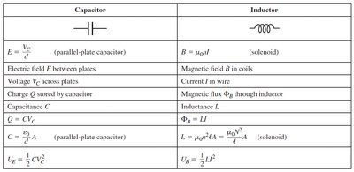
Summary Table: Capacitor vs. Inductor
Capacitor | Inductor |
|---|---|
(parallel-plate capacitor) | (solenoid) |
Electric field between plates | Magnetic field in coils |
Voltage across plates | Current in wire |
Charge stored by capacitor | Magnetic flux through inductor |
Capacitance | Inductance |
(parallel-plate capacitor) | (solenoid) |
