 Back
BackAlternating Current (AC) Circuits: Concepts, Analysis, and Applications
Study Guide - Smart Notes
 Tailored notes based on your materials, expanded with key definitions, examples, and context.
Alternating Current (AC) Circuits
Introduction to Alternating Current
Alternating current (AC) is a type of electrical current in which the direction of flow of electrons reverses periodically. AC is the standard for household and industrial power distribution due to its efficiency in long-distance transmission and ease of voltage transformation.
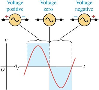
AC Source: A device that supplies a sinusoidally varying voltage.
Frequency (f): The number of cycles per second, measured in hertz (Hz). In the US and Canada, f = 60 Hz.
Voltage and Current: The instantaneous voltage and current in an AC circuit are described by sinusoidal functions.

Voltage Equation:
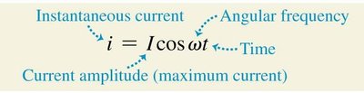
Current Equation:
Where and are the amplitudes, is the angular frequency, and is time.
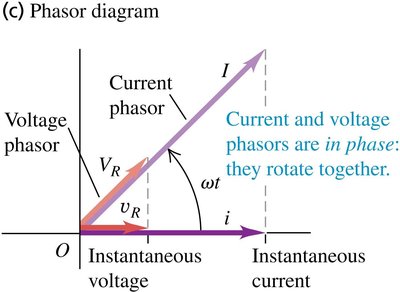
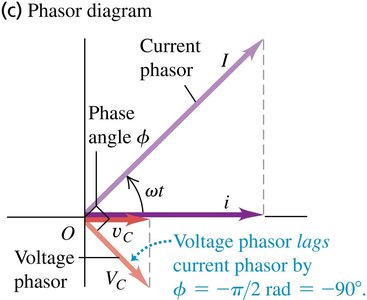
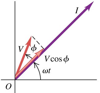
Phasor Representation
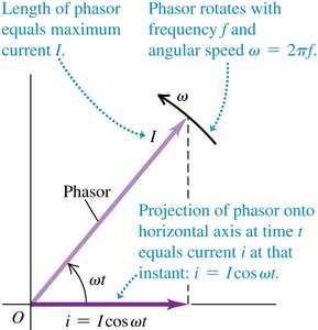
Phasors are rotating vectors used to represent sinusoidally varying quantities such as voltage and current. They simplify the analysis of AC circuits by converting differential equations into algebraic equations.
Phasor Diagram: The length of the phasor represents the amplitude, and its projection onto the horizontal axis gives the instantaneous value.
Angular Speed: The phasor rotates with angular speed .
Root-Mean-Square (RMS) Values
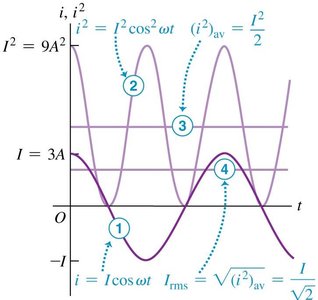
The root-mean-square (rms) value of a sinusoidal current or voltage is a measure of its effective value, equivalent to the value of a direct current or voltage that would produce the same average power in a resistor.
Calculation Steps:
Graph the current versus time.
Square the instantaneous current.
Take the average value of the squared current.
Take the square root of that average.
RMS Current:
RMS Voltage:


AC Circuit Elements
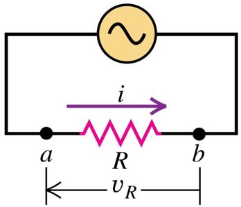
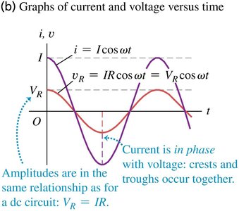
Resistor in an AC Circuit
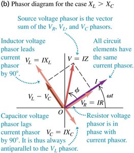
When a resistor is connected to an AC source, the voltage and current are in phase, and their amplitudes are related by Ohm's law.
Ohm's Law (AC):
Frequency Independence: The resistance does not depend on the frequency of the AC source.

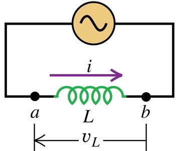
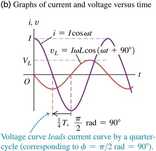
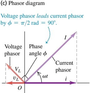
Inductor in an AC Circuit
When an inductor is connected to an AC source, the voltage leads the current by 90°, and the opposition to current is described by inductive reactance.
Inductive Reactance:
Voltage Across Inductor:
Frequency Dependence: The higher the frequency or inductance, the greater the reactance.

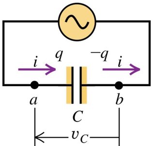
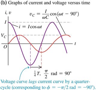
Capacitor in an AC Circuit
When a capacitor is connected to an AC source, the voltage lags the current by 90°, and the opposition to current is described by capacitive reactance.
Capacitive Reactance:
Voltage Across Capacitor:
Frequency Dependence: The higher the frequency or capacitance, the smaller the reactance.

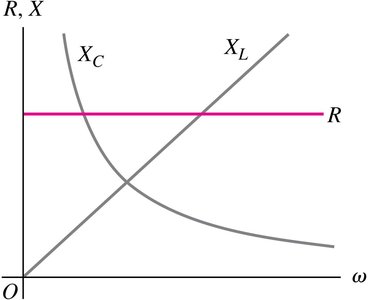
Comparison of AC Circuit Elements
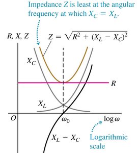
The resistance of a resistor is independent of frequency, while the reactances of inductors and capacitors vary with angular frequency .
Resistor: is constant.
Inductor: increases with .
Capacitor: decreases with .
At (DC), (no current through capacitor).
At , (no current through inductor).
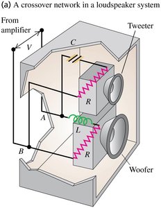
Application: Loudspeaker Crossover Networks
Loudspeaker systems use capacitors and inductors to direct different frequency signals to the appropriate speakers (woofer and tweeter).
Capacitor: Blocks low-frequency signals, passes high-frequency signals to the tweeter.
Inductor: Blocks high-frequency signals, passes low-frequency signals to the woofer.
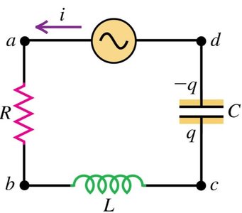
L-R-C Series Circuit
Impedance and Phasor Diagrams
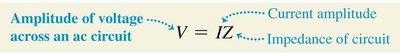
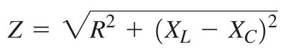
When a resistor, inductor, and capacitor are connected in series with an AC source, the total opposition to current is called impedance (), which combines resistance and reactance.
Impedance:
Voltage-Amplitude Relation:
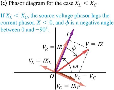
Phasor Diagrams: Show the vector sum of voltage drops across each element.
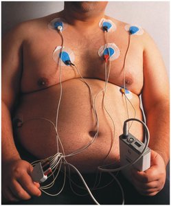
Application: Bioelectric Impedance Analysis
Bioelectric impedance analysis uses a small AC voltage to measure body composition by analyzing the amplitude and phase of the resulting current, which depends on the relative amounts of water and fat in the body.
Power in AC Circuits
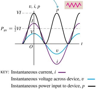
Power in a Resistor
For a pure resistor, voltage and current are in phase, and the instantaneous power is always positive.
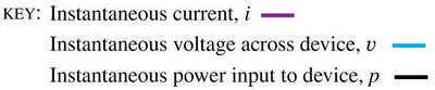
Instantaneous Power:
Average Power:
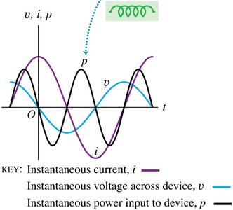
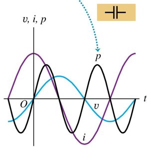
Power in an Inductor or Capacitor
For a pure inductor or capacitor, the voltage and current are out of phase by 90°, resulting in an average power of zero.
Inductor: Voltage leads current by 90°.
Capacitor: Voltage lags current by 90°.
Average Power:
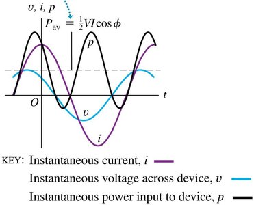
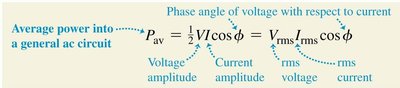
Power in a General AC Circuit
For circuits with any combination of resistors, inductors, and capacitors, the average power depends on the phase angle between voltage and current. The power factor quantifies the fraction of power delivered to the load.
Average Power:
Power Factor: (equals 1 for a pure resistor)
Resonance in AC Circuits
Resonance and Resonant Frequency
Resonance occurs in an L-R-C series circuit when the inductive and capacitive reactances are equal (), resulting in minimum impedance and maximum current amplitude. The frequency at which this occurs is the resonance angular frequency .
Resonance Condition:
Resonance Angular Frequency:
At Resonance: (minimum impedance)
Transformers
Principle and Applications
Transformers are devices that transfer electrical energy between two or more coils through electromagnetic induction. They are essential for efficiently transmitting AC power over long distances by stepping voltage up or down.
Step-Up Transformer: Increases voltage from primary to secondary coil ().
Step-Down Transformer: Decreases voltage from primary to secondary coil ().
Voltage Ratio:
Example: Power transmission lines use step-up transformers to increase voltage for long-distance transmission, reducing energy loss, and step-down transformers to lower voltage for safe use in homes.
