 Back
BackAlternating Current (AC) Circuits: Concepts, Analysis, and Applications
Study Guide - Smart Notes
 Tailored notes based on your materials, expanded with key definitions, examples, and context.
Alternating Current (AC) Circuits
Introduction to Alternating Current
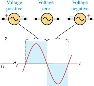
Alternating current (AC) is a type of electrical current in which the direction of flow of electrons reverses periodically. AC is the standard for household and industrial power distribution due to its efficiency in long-distance transmission and ease of voltage transformation. AC circuits are characterized by sinusoidally varying voltages and currents, which can be described mathematically and analyzed using specialized techniques.

Sinusoidal Voltages and Currents
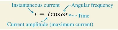
AC sources supply voltages that vary sinusoidally with time. The general form for the instantaneous voltage and current in an AC circuit is:
Voltage:
Current:
Where:
and are the amplitude (maximum value) of voltage and current, respectively.
is the angular frequency, with as the frequency in hertz (Hz).
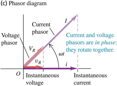
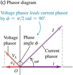
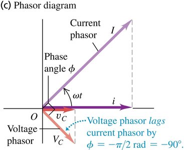
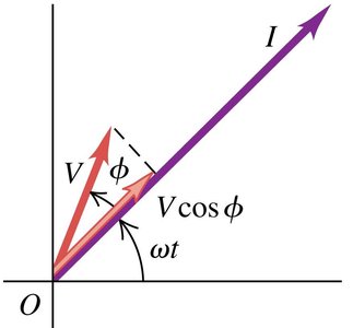
Phasor Representation
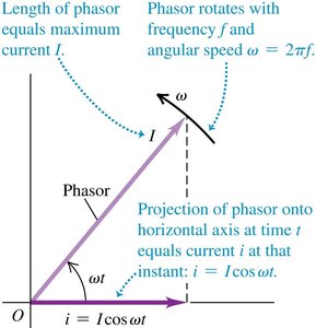
Phasors are rotating vectors used to represent sinusoidally varying quantities in AC circuits. They simplify the analysis of AC circuits by converting time-dependent functions into rotating vectors in a complex plane.
Phasor length: Represents the amplitude of the current or voltage.
Rotation: The phasor rotates with angular speed .
Projection: The projection of the phasor onto the horizontal axis at time gives the instantaneous value.
Root-Mean-Square (RMS) Values
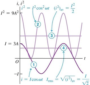
RMS values are used to express the effective or equivalent DC value of an AC current or voltage. The RMS value is particularly useful for calculating power in AC circuits.
RMS Current:
RMS Voltage:
Calculation steps:
Square the instantaneous value.
Take the mean (average) over a cycle.
Take the square root of the mean.


AC Circuit Elements
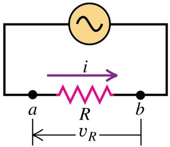
Resistor in an AC Circuit
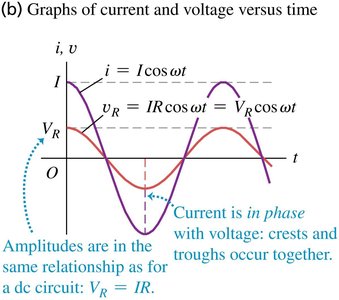
When a resistor is connected to an AC source, the voltage and current are in phase, and their amplitudes are related by Ohm's law:
Ohm's Law (AC):
Current and voltage: Both reach their maximum and minimum values simultaneously.
Frequency dependence: The resistance does not depend on the frequency of the AC source.

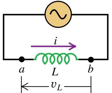
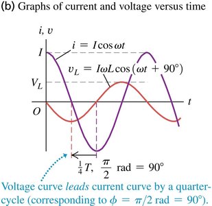
Inductor in an AC Circuit
When an inductor is connected to an AC source, the voltage leads the current by 90°, and the relationship between voltage and current involves the inductive reactance :
Inductive Reactance:
Voltage amplitude:
Frequency dependence: increases with frequency and inductance.

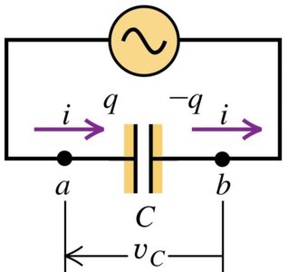
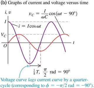
Capacitor in an AC Circuit
When a capacitor is connected to an AC source, the voltage lags the current by 90°, and the relationship involves the capacitive reactance :
Capacitive Reactance:
Voltage amplitude:
Frequency dependence: decreases with increasing frequency and capacitance.

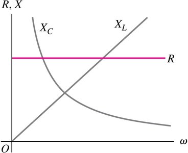
Comparison of AC Circuit Elements
The behavior of resistors, inductors, and capacitors in AC circuits varies with frequency. The resistance is independent of frequency, while the reactances and depend on frequency in opposite ways.
At low frequency (): ,
At high frequency (): ,
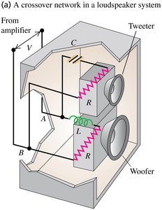
Application: Loudspeaker Crossover Networks
Loudspeaker systems use capacitors and inductors to direct different frequency signals to the appropriate speakers (tweeter for high frequencies, woofer for low frequencies). The capacitor blocks low frequencies from the tweeter, while the inductor blocks high frequencies from the woofer.
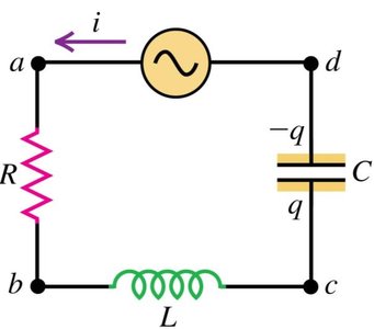
L-R-C Series Circuits
Impedance and Phasor Diagrams
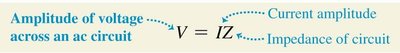
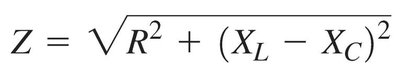
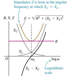
In a series circuit containing a resistor (), inductor (), and capacitor (), the total opposition to current is called the impedance ():
Impedance:
Voltage amplitude:
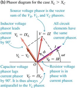
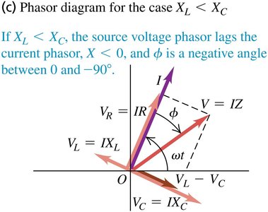
Phasor diagrams: Show the vector sum of voltage drops across each element.
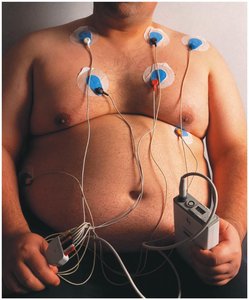
Application: Bioelectric Impedance Analysis
Bioelectric impedance analysis uses a small AC voltage to measure body composition. The amplitude and phase of the resulting current depend on the body's water and fat content, providing a non-invasive method for estimating body fat percentage.
Power in AC Circuits
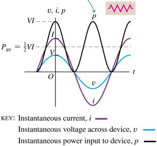
Power in a Resistor
For a pure resistor, voltage and current are in phase, and the instantaneous power is always positive. The average power delivered is:
Instantaneous power:
Average power:
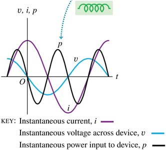
Power in an Inductor
For a pure inductor, the voltage leads the current by 90°, resulting in alternating positive and negative power. The average power over a cycle is zero, meaning no net energy is dissipated.
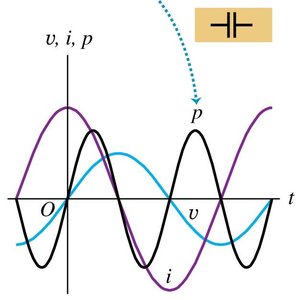
Power in a Capacitor
For a pure capacitor, the voltage lags the current by 90°, and the average power over a cycle is also zero.
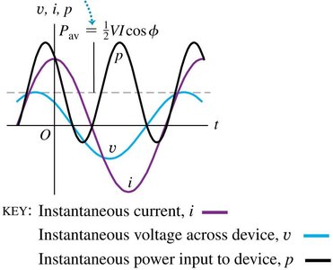
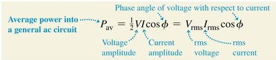
Power in a General AC Circuit
In circuits with combinations of resistors, inductors, and capacitors, the average power depends on the phase angle between the voltage and current. The power factor quantifies the fraction of power that does useful work.
Average power:
Power factor: (equals 1 for a pure resistor)
Resonance in AC Circuits
Resonance and Resonant Frequency
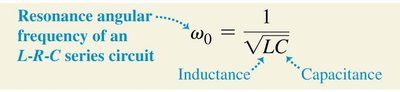
Resonance occurs in an L-R-C series circuit when the inductive and capacitive reactances are equal (), resulting in minimum impedance and maximum current. The resonant angular frequency is given by:
Resonant frequency:
At resonance: (minimum impedance)
Transformers
Principle and Applications
Transformers are devices that transfer electrical energy between two or more coils through electromagnetic induction. They are essential for efficiently transmitting AC power over long distances by stepping voltage up or down.
Step-up transformer: Increases voltage ()
Step-down transformer: Decreases voltage ()
Voltage ratio: , where and are the number of turns in the primary and secondary coils, respectively.
Example: Power distribution systems use step-up transformers to increase voltage for transmission and step-down transformers to reduce voltage for safe use in homes.
Transformer Type | Condition | Effect on Voltage |
|---|---|---|
Step-up | ||
Step-down |
