 Back
BackCapacitance and Dielectrics: Principles, Calculations, and Applications
Study Guide - Smart Notes
 Tailored notes based on your materials, expanded with key definitions, examples, and context.
Capacitance and Dielectrics
Introduction to Capacitance
Capacitance is a fundamental concept in electromagnetism, describing the ability of a system to store electric charge. Capacitors are widely used in electronic circuits for energy storage, filtering, and signal processing.
Capacitor: A device consisting of two conductors (plates) separated by an insulator, used to store electric charge and energy.
Capacitance (C): Defined as the ratio of the magnitude of charge (Q) on either conductor to the potential difference (ΔV) between the conductors.
The SI unit of capacitance is the farad (F), where 1 F = 1 C/V.
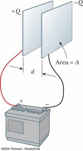
Physical Structure of a Capacitor
A typical capacitor consists of two parallel plates connected to a voltage source. When connected, one plate accumulates positive charge (+Q) and the other negative charge (−Q), creating a potential difference across the plates.
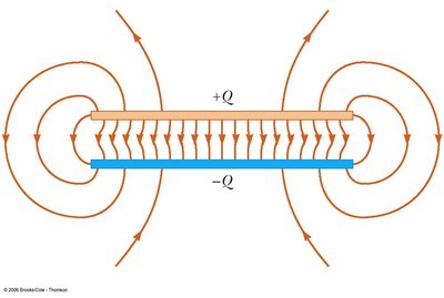
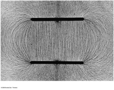
Electric Field in a Parallel-Plate Capacitor
The electric field between the plates of a parallel-plate capacitor is uniform (except near the edges) and is responsible for the potential difference between the plates.
Surface charge density: , where A is the area of each plate.
Electric field: , where is the permittivity of free space.
Potential difference:
Capacitance:
Capacitance of Other Geometries
Spherical Capacitor
A spherical capacitor consists of two concentric spherical conductors. The capacitance depends on the radii of the spheres.
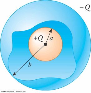
Capacitance: , where a and b are the radii of the inner and outer spheres, respectively.
Cylindrical Capacitor
A cylindrical capacitor consists of two coaxial cylinders. The capacitance depends on the length and radii of the cylinders.
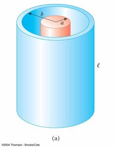
Capacitance: , where l is the length, a is the inner radius, and b is the outer radius.
Capacitors in Circuits
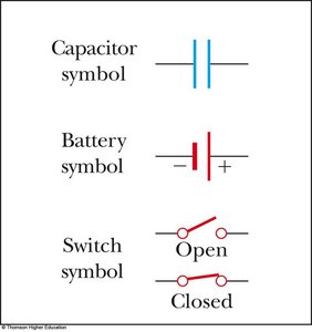
Circuit Symbols
Capacitors, batteries, and switches are represented by standard symbols in circuit diagrams.
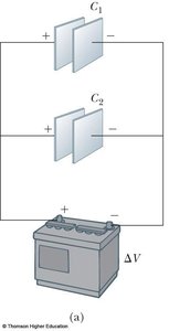
Capacitors in Series
When capacitors are connected in series, the reciprocal of the equivalent capacitance is the sum of the reciprocals of the individual capacitances. The charge on each capacitor is the same, but the voltage divides among them.
Equivalent capacitance (series):
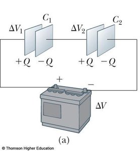
Capacitors in Parallel
When capacitors are connected in parallel, the equivalent capacitance is the sum of the individual capacitances. The voltage across each capacitor is the same, but the charge divides among them.
Equivalent capacitance (parallel):
Energy Stored in a Capacitor
Capacitors store energy in the electric field between their plates. The energy stored is given by:
Energy density (parallel-plate):
Applications of Capacitors
Defibrillators: Deliver a quick pulse of energy to restore normal heart rhythm.
Camera Flashes: Store energy for rapid discharge to produce a flash of light.
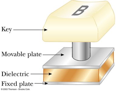
Computers: Used in keyboards and memory circuits to detect key presses and store data.
Dielectrics and Capacitance
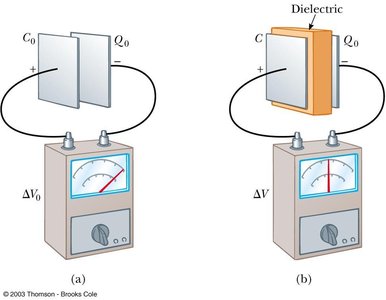
A dielectric is a nonconducting material placed between the plates of a capacitor to increase its capacitance. The dielectric constant (κ) quantifies this increase.
Capacitance with dielectric:
Dielectric constant (κ): Dimensionless property of the material.
Dielectric strength: Maximum electric field a dielectric can withstand without breakdown.
Types of Capacitors
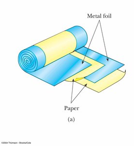
Tubular capacitors: Made by rolling metallic foil and paper into a cylinder.
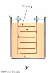
Oil-filled capacitors: Used for high-voltage applications, with plates immersed in oil.
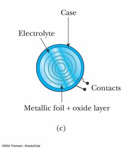
Electrolytic capacitors: Store large amounts of charge at low voltages, using an electrolyte.
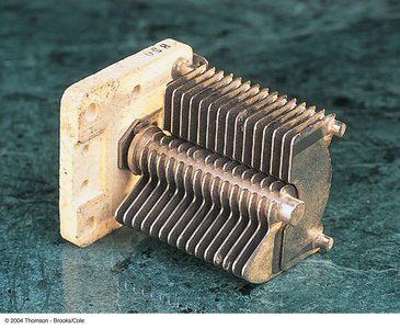
Variable capacitors: Capacitance can be adjusted, commonly used in radio tuning circuits.
Atomic Description of Dielectrics
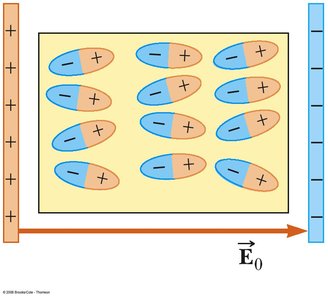
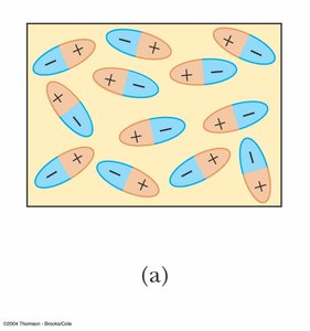
Dielectrics increase capacitance by reducing the effective electric field between the plates. This occurs due to polarization of the dielectric material, which can involve both polar and nonpolar molecules.
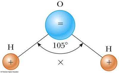
Polar molecules: Have a permanent separation of charge (e.g., water).
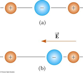
Nonpolar molecules: Can be polarized by an external electric field, inducing a dipole moment.
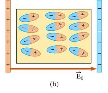
Polarization in Dielectrics
When a dielectric is placed in an electric field, its molecules align with the field, creating an induced electric field that opposes the original field. This reduces the net field and increases the capacitance.
Summary Table: Series vs. Parallel Capacitor Combinations
Property | Series | Parallel |
|---|---|---|
Charge | Same on each () | Adds () |
Voltage | Adds () | Same across each () |
Capacitance |
Worked Example: Inserting a Dielectric
Suppose a parallel-plate capacitor with area and separation is charged to . After disconnecting the power supply, a dielectric is inserted, reducing the voltage to while the charge remains constant. The following quantities can be calculated:
Original capacitance:
Charge:
New capacitance:
Dielectric constant:
Permittivity:
Induced charge:
Original electric field:
Electric field with dielectric:
Key Equations
(parallel-plate)
(with dielectric)
(energy stored)
(energy density)
Additional info: The notes above include expanded explanations, definitions, and context for all major concepts in the provided materials, as well as relevant equations and applications. Images were included only where they directly reinforce the explanation of the adjacent paragraph.
