 Back
BackCapacitance, Current, and Resistance: Foundations and Applications
Study Guide - Smart Notes
 Tailored notes based on your materials, expanded with key definitions, examples, and context.
Capacitors and Capacitance
Introduction to Capacitors
Capacitors are fundamental electrical components that store electric charge and energy. They consist of two conducting electrodes separated by an insulator (dielectric). The ability of a capacitor to store charge per unit potential difference is called its capacitance.
Capacitor Structure: Two electrodes (plates) separated by an insulator (air, glass, oil, etc.).
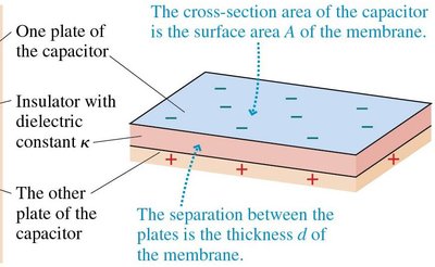
Example: The cell membrane acts as a parallel-plate capacitor, with the membrane as the dielectric.
Charging and Discharging a Capacitor
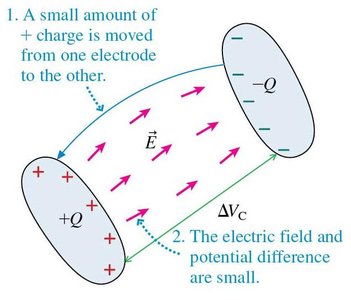
When a capacitor is connected to a battery, charge accumulates on the plates until the potential difference across the capacitor equals the battery voltage. If disconnected, the charge remains fixed.
Potential Difference: for a parallel-plate capacitor, where is plate area, is separation, and is the vacuum permittivity.
Charge-Voltage Relationship:
Capacitance: (for parallel plates)

Capacitance: Definition and Units
Capacitance () is a measure of a capacitor's ability to store charge per unit voltage. It depends only on the geometry and dielectric properties of the capacitor, not on the charge or voltage.
Unit: Farad (F), where
General Formula:
Examples of Capacitors
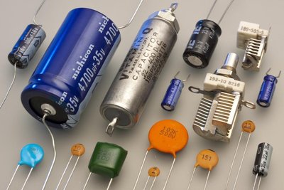
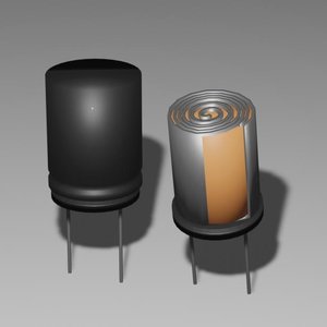
Capacitors come in various shapes and sizes, including cylindrical and parallel-plate types. They are widely used in electronics for energy storage, filtering, and timing applications.
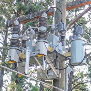
Applications: Camera flashes, defibrillators, power grids.


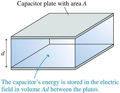
Energy Stored in a Capacitor
When a capacitor is charged, energy is stored in the electric field between its plates. The energy required to move charge onto the plates is given by:
Energy Formulae:
Energy Density: where is the electric field magnitude.
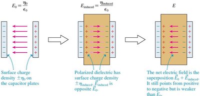
Dielectrics and Capacitance
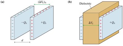
Dielectrics are insulating materials placed between capacitor plates to increase capacitance. They reduce the effective electric field, allowing more charge to be stored for the same voltage.
Dielectric Constant (): , where is the capacitance without dielectric.
Effect: Increases capacitance, reduces voltage for fixed charge.
Material | Dielectric Constant (K) |
|---|---|
Vacuum | 1 (exactly) |
Air | 1.00054 |
Teflon | 2.0 |
Paper | 3.0 |
Pyrex glass | 4.8 |
Cell membrane | 9.0 |
Ethanol | 24 |
Water | 80 |
Strontium titanate | 300 |
Applications: Biological Membranes as Capacitors
Cell Membrane as a Capacitor
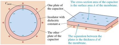
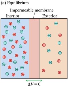
The cell membrane can be modeled as a parallel-plate capacitor, with the lipid bilayer acting as the dielectric. Ion pumps and channels create charge separation, leading to a potential difference across the membrane.
Ion Pumps: Actively transport ions, maintaining a voltage difference (membrane potential).
Capacitance Formula: , where is the cell surface area and is membrane thickness.
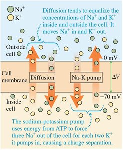
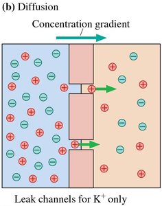
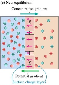
Nernst Potential and Ion Equilibrium
The equilibrium potential difference across a membrane (Nernst potential) is determined by the concentration gradient of ions and temperature:
Nernst Equation:
Variables: = temperature (K), = Boltzmann constant, = elementary charge, and = ion concentrations outside and inside the cell.
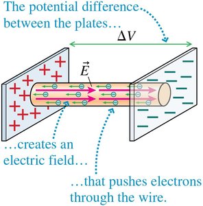
Electric Current and Resistance
Electric Current
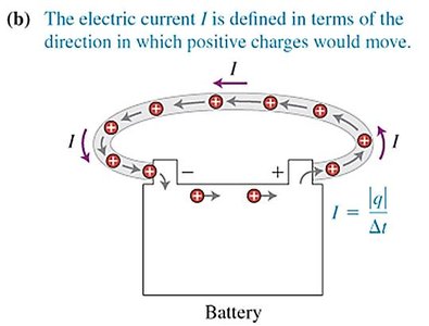
Electric current is the flow of electric charge. It is quantified as the amount of charge passing through a cross-section per unit time.
Current Formula:
Unit: Ampere (A), where
Direction: By convention, current direction is the direction positive charges would move.
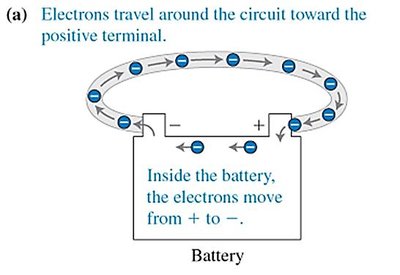
Electric Circuits
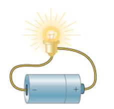
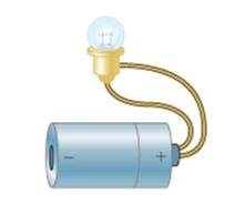
An electric circuit is a closed loop that allows continuous flow of charge. For current to flow, the circuit must be complete (no breaks).
Example: Battery and lightbulb circuit; bulb lights up only if the circuit is closed.


Resistance and Ohm's Law
Resistance is the opposition to the flow of electric current. Ohm's law relates current, voltage, and resistance in many materials:
Ohm's Law: or
Unit: Ohm (), where
Microscopic Origin: Collisions of electrons with ions in a conductor impede flow.
Resistivity and Conductivity
The resistance of a wire depends on its material, length, and cross-sectional area. Resistivity () is a material property; conductivity () is its reciprocal.
Resistance Formula:
Conductivity:
Units: in , in S/m (siemens per meter)
Material | Resistivity () | Conductivity (S/m) |
|---|---|---|
Copper | 1.7 × 10⁻⁸ | 5.9 × 10⁷ |
Aluminum | 2.8 × 10⁻⁸ | 3.5 × 10⁷ |
Glass | 1010–1014 | 10−14–10−10 |
Rubber | 1013 | 10−13 |
Power in Electric Circuits
Electric power is the rate at which energy is supplied or consumed in a circuit. For a resistor, power can be expressed in several equivalent forms:
Power Formulae:
(battery)
(resistor)
Circuit Diagrams and Ideal Wires
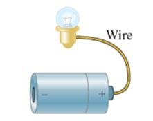
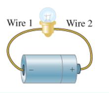
Circuit diagrams are simplified representations of electrical circuits. In the ideal-wire model, wires are assumed to have zero resistance, and all points along a wire are at the same potential.
Charge Conservation: Current is the same through all elements in a single-loop circuit.
Current Flow: Current is not "used up"; it stops only if the circuit is opened.
Additional info: This guide covers the core concepts of capacitance, current, and resistance, including biological applications and practical circuit analysis, as outlined in college-level physics courses.
