 Back
BackChapter 17: Wave Optics – Study Guide
Study Guide - Smart Notes
 Tailored notes based on your materials, expanded with key definitions, examples, and context.
Wave Optics
What is Light?
Light is a fundamental phenomenon in physics, described as an electromagnetic wave consisting of oscillating electric and magnetic fields. The speed of light in a vacuum is a universal constant, and its wavelength determines its color in the visible spectrum.
Electromagnetic Wave: Light is composed of electric and magnetic fields oscillating perpendicular to each other and to the direction of propagation.
Speed of Light: In a vacuum, light travels at m/s.
Visible Spectrum: Wavelengths range from 400 nm (violet) to 700 nm (red).
Frequency Calculation: For a wavelength , frequency is .
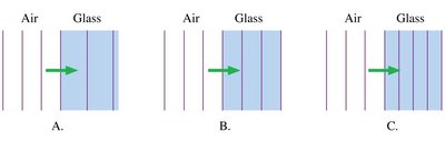
The Index of Refraction
When light passes through transparent materials, its speed decreases due to interactions with the material's electrons. This effect is quantified by the index of refraction, .
Definition: , where is the speed of light in the material.
Properties: ; for a vacuum, .
Material | Index of Refraction |
|---|---|
Vacuum | 1.00 |
Air | 1.0003 |
Water | 1.33 |
Glass | 1.50 |
Diamond | 2.42 |
Example: Orange light (600 nm) entering glass () slows to m/s, and its wavelength shortens to 400 nm.
The Interference of Light
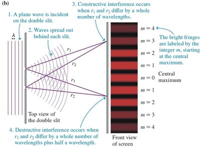
Young’s Double-Slit Experiment
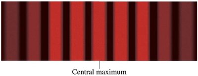
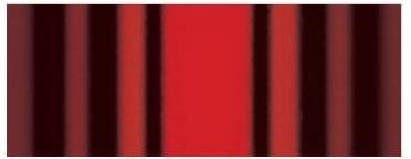
Young's experiment demonstrates the wave nature of light through interference. Light passing through two narrow slits produces a pattern of bright and dark fringes on a screen.
Constructive Interference: Occurs when the path difference between the two slits is an integer multiple of the wavelength ().
Destructive Interference: Occurs when the path difference is a half-integer multiple ().
Fringe Order: Bright fringes are labeled by integer .
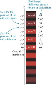
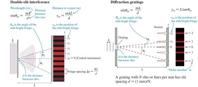
Analyzing Double-Slit Interference
The positions of bright and dark fringes can be calculated using the geometry of the setup and the wavelength of light.
Bright Fringe Condition:
Small Angle Approximation: For small , .
Fringe Spacing: , where is the distance to the screen and is the slit separation.
Dark Fringe Location: Dark fringes are halfway between bright fringes.
Factors Affecting Fringe Patterns
Screen Distance: Moving the screen farther increases fringe spacing.
Wavelength: Using shorter wavelengths (e.g., green light) decreases fringe spacing.
Slit Separation: Decreasing slit separation increases fringe spacing.


Measuring the Wavelength of Light
By measuring the distance between fringes and knowing the slit separation and screen distance, the wavelength of light can be determined.
Fringe Spacing:
Application: Used in laboratory experiments to measure unknown wavelengths.

The Diffraction Grating
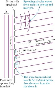
Principles of Diffraction Gratings
A diffraction grating consists of many closely spaced slits, producing sharper and more numerous interference maxima than a double-slit.
Constructive Interference: Occurs when for integer .
Order of Diffraction: indicates the order of the maximum.
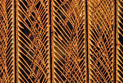
Diffraction from Natural Structures
Structures such as feather barbules act as natural diffraction gratings, producing colorful patterns due to interference.
Spacing: The spacing between structures determines the diffraction angles.
Example: For 50 barbules per mm, m.
First-order Angles: For blue light (450 nm), ; for red light (650 nm), .
Comparison: Double-Slit vs. Diffraction Grating
Both devices rely on the same principle: constructive interference occurs when the path-length difference is an integer multiple of the wavelength.
Device | Interference Condition | Fringe Pattern |
|---|---|---|
Double-Slit | Equally spaced bright fringes | |
Diffraction Grating | Sharp, narrow maxima |
Single-Slit Diffraction
Huygens’ Principle and Diffraction
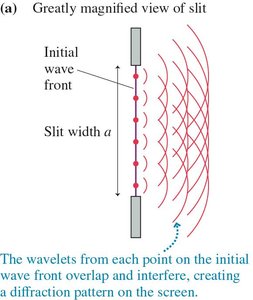
Single-slit diffraction arises from the interference of wavelets originating from different points across the slit width. The resulting pattern features a broad central maximum and diminishing side maxima.
Huygens’ Principle: Every point on a wave front acts as a source of spherical wavelets.
Interference: Wavelets overlap and interfere, producing the observed pattern.
Analyzing Single-Slit Diffraction
The positions of minima (dark fringes) are determined by the slit width and wavelength.
Minima Condition: ,
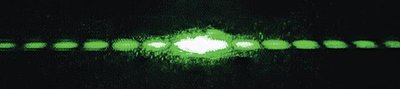
Central Maximum: The central maximum at is the brightest.
Intensity Variation: Intensity decreases smoothly between minima.
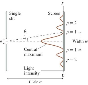
Width of the Single-Slit Diffraction Pattern
The width of the central maximum is determined by the distance between the first minima on either side.
Distance to Minima:
Width of Central Maximum:
Effect of Slit Width: Narrower slits produce wider central maxima.


Babinet’s Principle
Babinet’s principle states that the diffraction pattern from an opaque object is identical to that from a slit of the same size.
Application: A thin wire produces the same pattern as a slit of equal width.
Factors Affecting Single-Slit Diffraction
Slit Width: Making the slit narrower increases the width of the central maximum.
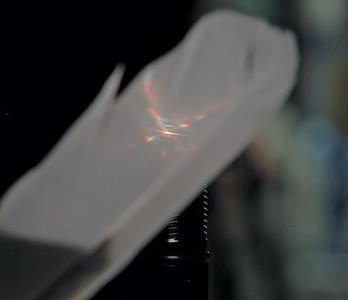
Using Diffraction to Measure Small Widths
Diffraction can be used to measure the width of thin objects, such as a human hair, by analyzing the width of the central maximum in the diffraction pattern.
Equation: , where is the width, is the wavelength, is the distance to the screen, and is the width of the central maximum.
Example: A 530 nm laser produces a 14 mm central maximum at 1.2 m; the hair width is calculated to be 91 μm.
Effect of Width: A wider hair produces a narrower central maximum.
