 Back
BackChapter 18: Ray Optics – Study Notes
Study Guide - Smart Notes
 Tailored notes based on your materials, expanded with key definitions, examples, and context.
Ray Optics
Introduction to Ray Optics
Ray optics, also known as geometric optics, is a model of light that treats light as traveling in straight lines called rays. This model is valid when apertures are larger than about 1 mm and ignores diffraction effects. Ray optics is essential for understanding phenomena such as reflection, refraction, and image formation by mirrors and lenses.
The Ray Model of Light
Properties of Light Rays
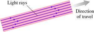
Light rays are idealized lines indicating the direction of energy flow. They travel in straight lines through a vacuum or transparent materials. The speed of light in a material is given by:
where c is the speed of light in vacuum and n is the index of refraction.
Light rays can cross without interacting.
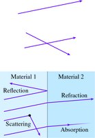
Light rays continue indefinitely unless they interact with matter (reflection, refraction, scattering, absorption).
Sources of Light Rays
Self-luminous objects (e.g., lightbulbs, the sun) emit their own light.
Reflective objects (e.g., paper, trees) reflect light from other sources.
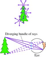
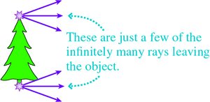
Each point on an object emits rays in all directions.
Ray Diagrams
Ray diagrams simplify the analysis by showing only a few representative rays, though in reality rays originate from every point and travel in all directions.
Seeing Objects and Shadows
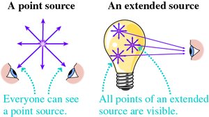
Visibility of Light Sources
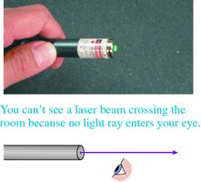
To see an object, rays from it must enter the eye.
Point and extended sources emit rays in all directions, making them visible from any location.
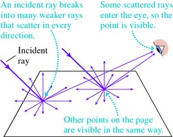
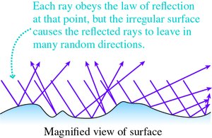
Diffuse Reflection and Scattering
Diffuse reflection: Incident light is reflected in all directions from rough surfaces.
Scattering: Single rays break into many weaker rays, leaving in all directions.
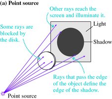
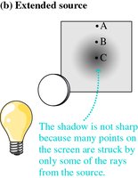
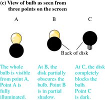
Shadows
Opaque objects block light, creating shadows.
Point sources produce sharp shadows; extended sources produce fuzzy shadows.
Reflection
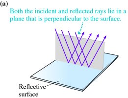
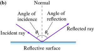
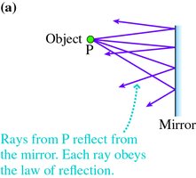
Law of Reflection
Reflection occurs when light bounces off a surface. The law of reflection states:
The incident ray and reflected ray are in the same plane perpendicular to the surface.
The angle of incidence equals the angle of reflection:
Diffuse Reflection
On rough surfaces, the law of reflection still holds, but rays are reflected in many directions due to surface irregularities.
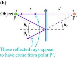
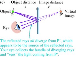
Plane Mirrors and Image Formation
Plane mirrors form virtual images located behind the mirror.
The image distance equals the object distance:
Refraction
Snell's Law
Refraction is the bending of light as it passes from one medium to another. Snell's law describes this behavior:
When entering a medium with higher index, light bends toward the normal.
When entering a medium with lower index, light bends away from the normal.
Total Internal Reflection
Occurs when light attempts to move from a medium with higher index to lower index at an angle greater than the critical angle.
All light is reflected back into the original medium.
Image Formation by Refraction and Lenses
Thin Lenses and Ray Tracing
Converging lenses: Refract rays toward the optical axis, forming real or virtual images.
Diverging lenses: Refract rays away from the axis, always forming virtual images.
The thin-lens equation relates object distance (s), image distance (s'), and focal length (f):
Magnification is given by:
Ray Tracing for Lenses
Three special rays are used: parallel to axis, through focal point, through center.
Real images are inverted; virtual images are upright.
Image Formation with Spherical Mirrors
Converging (Concave) and Diverging (Convex) Mirrors
Converging mirrors focus parallel rays to a focal point, forming real or virtual images.
Diverging mirrors cause rays to appear to diverge from a point behind the mirror, always forming virtual images.
Ray Tracing for Mirrors
Three special rays: parallel to axis (reflects through focal point), through focal point (reflects parallel), and through center (reflects at equal angle).
The Thin-Lens Equation and Sign Conventions
Thin-Lens Equation
The thin-lens equation applies to both lenses and curved mirrors:
Focal length (f): Positive for converging, negative for diverging.
Object distance (s): Always positive.
Image distance (s'): Positive for real images, negative for virtual images.
Magnification
Magnification describes the size and orientation of the image:
Absolute value gives size ratio.
Positive magnification: upright image.
Negative magnification: inverted image.
Summary Table: Types of Images and Sign Conventions
Type | Focal Length (f) | Image Distance (s') | Magnification (m) |
|---|---|---|---|
Converging Lens/Mirror (Real Image) | Positive | Positive | Negative |
Converging Lens/Mirror (Virtual Image) | Positive | Negative | Positive |
Diverging Lens/Mirror | Negative | Negative | Positive |
Applications
Fiber optics: Use total internal reflection to transmit light efficiently.
Magnifying glasses: Use converging lenses to produce virtual, upright, magnified images.
Rearview mirrors: Convex mirrors provide a wide field of view but smaller images.
Key Equations
Speed of light in a medium:
Snell's law:
Critical angle:
Thin-lens equation:
Magnification:
Conclusion
Ray optics provides a foundational understanding of how light interacts with matter, forms images, and is manipulated by optical devices. Mastery of these concepts is essential for further study in optics and practical applications in technology and everyday life.
