 Back
BackChapter 26: AC Electricity – Principles, Applications, and Safety
Study Guide - Smart Notes
 Tailored notes based on your materials, expanded with key definitions, examples, and context.
AC Electricity
Introduction to Alternating Current (AC)
Alternating Current (AC) is a type of electrical current in which the direction of flow reverses periodically, as opposed to Direct Current (DC), where the flow is unidirectional. AC is the standard for power distribution due to its efficiency in transmission and compatibility with transformers.
Direct Current (DC): Current flows in one direction only, typically produced by batteries.
Alternating Current (AC): Current reverses direction periodically, typically produced by generators.
AC Generation: Produced by rotating a coil in a magnetic field, resulting in a sinusoidal emf (electromotive force).
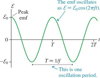
Mathematical Form: The instantaneous emf is given by: where is the peak emf, is the frequency, and is time.
Period (): The time for one complete cycle, .
Example: In the US, wall outlets provide AC at a peak of about 170 V and a frequency of 60 Hz.
AC Circuits with Resistors
Ohm’s Law and Notation in AC Circuits
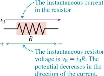
In AC circuits, voltage and current vary with time, but resistance remains constant. Notation distinguishes between time-varying (lowercase) and constant (uppercase) quantities.
Ohm’s Law (DC):
Ohm’s Law (AC, instantaneous):
Resistor in an AC Circuit
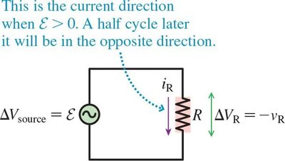
When a resistor is connected to an AC source, the current and voltage across the resistor oscillate in phase with the source emf.
Kirchhoff’s Loop Rule: The sum of potential differences around a closed loop is zero, just as in DC circuits.
Current Direction: The direction of current reverses with the emf.
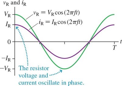
Voltage and Current Equations: where and are the peak voltage and current, respectively.
In-Phase Oscillation: Voltage and current reach their maxima and minima simultaneously.
AC Power in Resistors
Instantaneous and Average Power
The power dissipated in a resistor in an AC circuit varies with time, reaching a maximum twice per cycle. The average power is more useful for practical calculations.
Instantaneous Power:
Average Power:
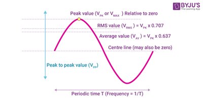
Root-Mean-Square (rms) Values: The rms value of a varying quantity is the square root of the mean of the squares of its instantaneous values.
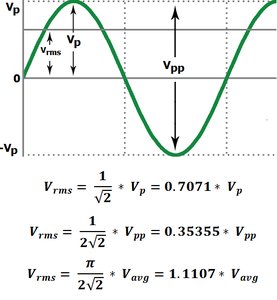
RMS Voltage and Current:
Comparison: All DC power equations apply to AC circuits if rms values are used.
Transformers and Power Transmission
Principle and Operation of Transformers
Transformers are devices that change the voltage and current levels in AC circuits using electromagnetic induction. They are essential for efficient power transmission over long distances.
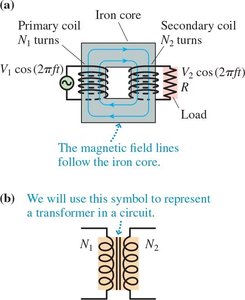
Structure: Consist of primary and secondary coils wound on a common iron core.
Operation: An alternating current in the primary coil creates a changing magnetic flux, inducing an emf in the secondary coil.
Voltage Relationship: where and are the number of turns in the primary and secondary coils, respectively.
Types: Step-up transformer () increases voltage; step-down transformer () decreases voltage.
Power Conservation (Ideal Transformer):

Power Transmission and Efficiency
High-voltage transmission reduces current and minimizes power loss in transmission lines. Multiple transformers are used to step up voltage for transmission and step it down for safe use in homes.
Transmission Process: Power plant (25 kV) → Step-up transformer (500 kV) → Transmission lines → Step-down transformer (7.2 kV) → Step-down transformer (120 V for homes).
Efficiency: Power loss in transmission lines is . Lower current (via higher voltage) reduces losses.
Household Electricity and Safety
Grounding and Electrical Outlets
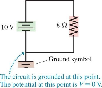
Grounding provides a reference potential (0 V) and a safe path for excess current. Household outlets are designed with safety features to minimize electrical hazards.
Outlet Design: Neutral (grounded) and hot sides; devices receive 120 V AC when plugged in.
Parallel Connection: Outlets are wired in parallel to maintain constant voltage.
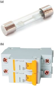
Circuit Protection: Circuit breakers and fuses disconnect the circuit if current exceeds safe limits (e.g., 15 A).
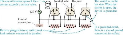
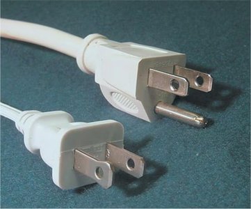
Three-Prong Plugs: The third prong provides a direct ground connection for metal-cased devices, enhancing safety.
Energy Consumption and Billing
Electricity usage is measured in kilowatt-hours (kWh), a unit of energy. Utility companies bill customers based on kWh consumed.
Energy Calculation:
Typical Usage: Average US home uses about 30 kWh per day.
Biological Effects and Electrical Safety
Current and Human Body
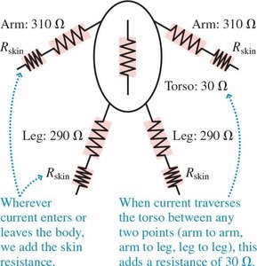
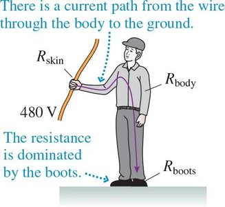
The danger of electricity is primarily determined by the current passing through the body, not just the voltage. The severity of effects depends on current magnitude, duration, and path through the body.
Thresholds: 15 mA (AC) can stop breathing; 100 mA (AC) can disrupt heart rhythm.
Body Resistance: Varies with skin condition (dry: ~100,000 Ω; wet: ~1,000 Ω).
Protective Equipment: Increases resistance and reduces current through the body.

Birds on Power Lines: Experience negligible potential difference between feet, so no harmful current flows.
Ground Fault Interrupters (GFI)
GFI outlets are used in wet areas to protect against dangerous ground faults. They disconnect the circuit if a small difference in current (about 5 mA) is detected between hot and neutral wires, indicating a possible leakage through a person.
Operation: Compares current in hot and neutral wires; disconnects if imbalance is detected.
Application: Required in kitchens, bathrooms, and outdoor outlets for enhanced safety.
*Additional info: GFI circuits are a critical safety feature in modern electrical systems, preventing fatal shocks in hazardous environments.*
