 Back
BackCurrent, Resistance, and Circuits: Study Notes for College Physics
Study Guide - Smart Notes
 Tailored notes based on your materials, expanded with key definitions, examples, and context.
Current, Resistance, and Circuits
Electric Current
Electric current is the flow of electric charge through a conductor, typically measured in amperes (A). In physics, current is defined as the rate at which charge passes through a given point:
Definition: , where is current, is the amount of charge, and is the time interval.
Direction: By convention, current is considered as the motion of positive charges, even though electrons (negative charges) are the actual charge carriers in most conductors.
Example: If a 10-A current flows through a wire for 2.0 minutes, the total charge transferred is C.
Resistance and Resistivity
Resistance is a property of a conductor that opposes the flow of electric current. Resistivity is a material-specific property that quantifies how strongly a material resists current flow.
Resistivity (): Low for good conductors (e.g., copper), high for insulators (e.g., pure water).
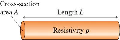
Resistance (): Depends on resistivity, length (), and cross-sectional area () of the wire: .
Example: A 25-m wire of diameter 0.30 mm draws 0.499 A when connected across a 3.0-V potential difference. Calculate resistance and resistivity using the above formula.
Ohm's Law
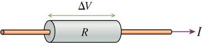
Ohm's Law describes the linear relationship between the potential difference across a resistor and the current flowing through it:
Formula:
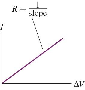
Ohmic Materials: Materials that obey Ohm's Law (linear vs relationship) are called ohmic.
Graph: The slope of the vs graph gives .
Energy and Power in Circuits
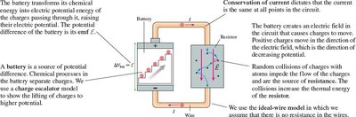
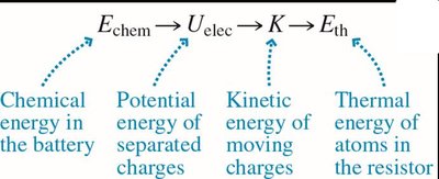
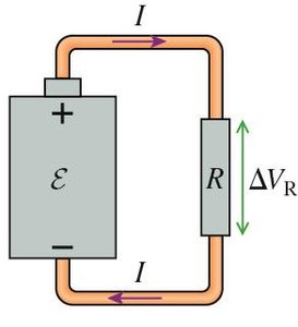
Energy in electric circuits is supplied by batteries and dissipated by resistors. The battery transforms chemical energy into electrical energy, which is then converted to thermal energy in resistors.
Power supplied by battery:
Power dissipated by resistor:
Energy transformations: Chemical energy → electrical potential energy → kinetic energy of charges → thermal energy.
Example: An instrument rated at 250 W connected across 120 V draws A.
Batteries in Series
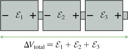
Batteries connected in series add their potential differences. The total voltage is the sum of individual battery voltages.
Formula:
Application: Used to increase the total voltage available to a circuit.
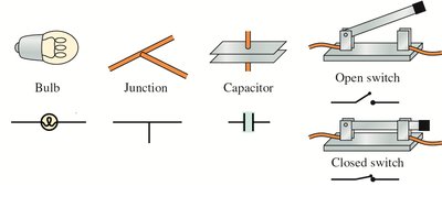
Circuit Elements and Diagrams
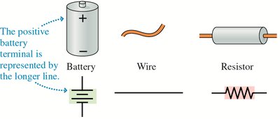
Electric circuits are represented using standardized symbols for batteries, wires, resistors, bulbs, junctions, capacitors, and switches.
Battery: Longer line represents positive terminal.
Wire: Straight line.
Resistor: Zigzag line.
Bulb, Junction, Capacitor, Switch: Specific symbols for each.
Kirchhoff's Laws
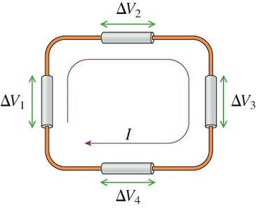
Kirchhoff’s Loop Law
Kirchhoff’s Loop Law states that the sum of potential differences around any closed loop in a circuit is zero. This is a consequence of energy conservation.
Formula:
Application: Used to analyze complex circuits with multiple loops.
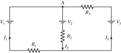
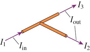
Kirchhoff’s Junction Law
Kirchhoff’s Junction Law states that the sum of currents entering a junction equals the sum of currents leaving the junction. This is a consequence of charge conservation.
Formula:
Application: Used to analyze current distribution in circuits.
Series and Parallel Circuits
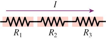
Series Elements
In a series connection, all elements share the same current. The total resistance is the sum of individual resistances.
Resistors in series:
Capacitors in series:
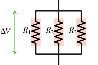
Parallel Elements
In a parallel connection, all elements share the same potential difference. The total resistance is found by the reciprocal sum of individual resistances.
Resistors in parallel:
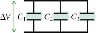
Capacitors in parallel:
Applications and Example Problems
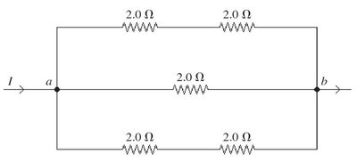
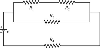
Complex circuits can be analyzed by reducing series and parallel combinations to equivalent values. Example problems include calculating equivalent resistance, charge on capacitors, and power dissipation.
Example: Five 2.0-Ω resistors are connected in a combination between points a and b. Find the equivalent resistance.
Applications: Electricity in the Nervous System
Action Potentials and Neurons
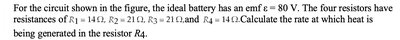
Cells in the nervous system use electrical potentials to transmit signals. The cell membrane maintains a negative potential, and when triggered, depolarizes to generate an action potential.
Action Potential: A rapid change in membrane potential that propagates along the axon.
Saltatory Conduction: Myelin insulation allows the action potential to jump from node to node, increasing speed.
Summary Table: Series vs Parallel Circuits
Property | Series | Parallel |
|---|---|---|
Current | Same through all elements | Divided among branches |
Voltage | Divided among elements | Same across all branches |
Resistors | ||
Capacitors |
Additional info: Academic context and explanations have been expanded for clarity and completeness. All images included are directly relevant to the adjacent content.
