 Back
BackCurrent, Resistance, and Electromotive Force (EMF): Study Notes
Study Guide - Smart Notes
 Tailored notes based on your materials, expanded with key definitions, examples, and context.
Current, Resistance, and Electromotive Force (EMF)
Electric Current
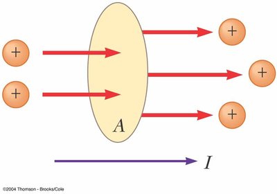
Electric current is the rate at which electric charge flows through a surface or conductor. It is a fundamental concept in understanding how electrical circuits operate.
Definition: Electric current (I) is defined as the amount of charge (Q) passing through a cross-sectional area (A) per unit time (t).
SI Unit: Ampere (A), where 1 A = 1 C/s.
Direction: By convention, current direction is the direction of positive charge flow, even though in metals, electrons (negative charges) are the actual charge carriers.
Formulas:
Average current:
Instantaneous current:
Current and Drift Speed
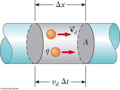
In a conductor, current is carried by charge carriers (typically electrons) moving with an average drift velocity due to an applied electric field.
Drift Velocity (vd): The average velocity at which charge carriers move through a conductor under the influence of an electric field.
Number Density (n): Number of charge carriers per unit volume.
Charge per Carrier (q): For electrons, q = -e.
Current Formula:
Microscopic View of Current
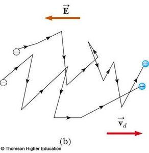
On a microscopic level, electrons move randomly but acquire a net drift velocity in the presence of an electric field, resulting in a current.
Electrons undergo frequent collisions with atoms, causing a zigzag path.
The net motion (drift) is opposite to the electric field for electrons.
Current Density
Current density (J) is the current per unit area of cross-section in a conductor.
Formula:
SI Unit: A/m2
Direction: Same as the direction of positive charge flow and the electric field.
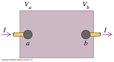
Ohm’s Law and Resistance
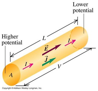
Ohm’s Law relates the current through a conductor to the voltage across it and its resistance. It is an empirical law valid for many materials (ohmic materials).
Ohm’s Law:
Resistance (R): Opposition to current flow, measured in ohms (Ω).
Resistivity (ρ): A material property, , where L is length and A is cross-sectional area.
Conductivity (σ): Inverse of resistivity, .
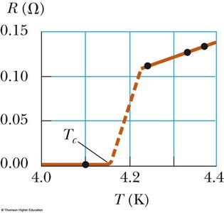
Temperature Dependence of Resistance
The resistance of most conductors increases with temperature. For some materials, such as semiconductors, resistance decreases with temperature.
Linear Approximation:
Temperature Coefficient (α): Indicates how resistivity changes with temperature.
Superconductors: Materials whose resistance drops to zero below a critical temperature (Tc).
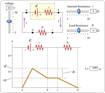
Electromotive Force (EMF) and Internal Resistance
Electromotive force (emf, ε) is the energy provided per unit charge by a source such as a battery. Real sources have internal resistance (r), which reduces the terminal voltage when current flows.
Terminal Voltage:
Current in Circuit:
Open Circuit: Terminal voltage equals emf when I = 0.
Electrical Power in Circuits
Electrical power is the rate at which energy is delivered to a component in a circuit, such as a resistor.
Power Delivered:
Unit: Watt (W), where 1 W = 1 J/s.
Energy Consumption: Electrical energy is often measured in kilowatt-hours (kWh).
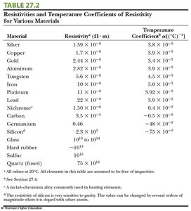
Summary Table: Resistivities and Temperature Coefficients
The following table summarizes the resistivities and temperature coefficients for various materials, which are essential for selecting materials in electrical applications.
Material | Resistivity (Ω·m) | Temperature Coefficient (°C-1) |
|---|---|---|
Silver | 1.59 × 10⁻⁸ | 3.8 × 10⁻³ |
Copper | 1.7 × 10⁻⁸ | 3.9 × 10⁻³ |
Gold | 2.44 × 10⁻⁸ | 3.4 × 10⁻³ |
Aluminum | 2.82 × 10⁻⁸ | 3.9 × 10⁻³ |
Iron | 1.0 × 10⁻⁷ | 6.5 × 10⁻³ |
Lead | 2.2 × 10⁻⁷ | 3.9 × 10⁻³ |
Carbon | 3.5 × 10⁻⁵ | -0.5 × 10⁻³ |
Silicon | 6.4 × 10² | -75 × 10-3 |
Glass | 1010 to 1014 | — |
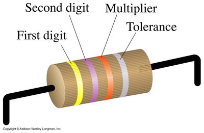
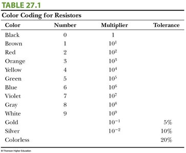
Color Coding for Resistors
Resistor values are often indicated by colored bands. Each color corresponds to a digit, multiplier, and tolerance.
Color | Number | Multiplier | Tolerance |
|---|---|---|---|
Black | 0 | 1 | |
Brown | 1 | 101 | |
Red | 2 | 102 | |
Orange | 3 | 103 | |
Yellow | 4 | 104 | |
Green | 5 | 105 | |
Blue | 6 | 106 | |
Violet | 7 | 107 | |
Gray | 8 | 108 | |
White | 9 | 109 | |
Gold | 10-1 | 5% | |
Silver | 10-2 | 10% | |
Colorless | 20% |
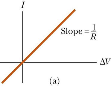
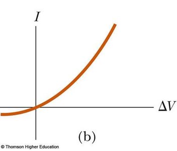
Ohmic and Nonohmic Materials
Ohmic materials have a linear relationship between current and voltage, while nonohmic materials do not.
Ohmic: (straight line on I-V graph)
Nonohmic: Nonlinear I-V relationship (e.g., diodes)
Applications: Power Transmission
Electric power is transmitted at high voltages and low currents to minimize energy loss due to resistance in transmission lines.

Additional info: These notes provide a comprehensive overview of electric current, resistance, Ohm's law, temperature effects, EMF, and power in circuits, suitable for college-level physics students preparing for exams.
