 Back
BackCurrent, Resistance, and Electromotive Force (EMF): Study Notes
Study Guide - Smart Notes
 Tailored notes based on your materials, expanded with key definitions, examples, and context.
Current, Resistance, and Electromotive Force (EMF)
Introduction
This chapter explores the fundamental concepts of electric current, resistance, and electromotive force (EMF) in electric circuits. Understanding these principles is essential for analyzing and designing electrical systems, from simple circuits to complex electronic devices.
Electric Current
Definition and Nature of Current
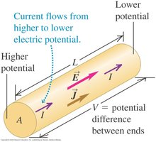
Electric current (I) is the rate at which charge flows through a surface. It is defined as , where is the amount of charge passing through a cross-section in time .
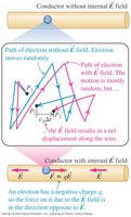
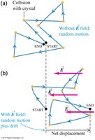
An electric field inside a conductor causes charges (typically electrons) to move, resulting in current.
The SI unit of current is the ampere (A), where 1 A = 1 C/s.
Direction of Current Flow
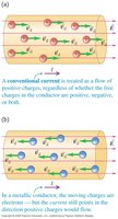
Current can be due to the flow of positive or negative charges.
Conventional current is defined as the direction positive charges would move, even though in metals, electrons (negative charges) are the actual charge carriers.
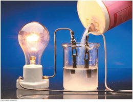
Current in Solutions
In electrolytic solutions, both positive and negative ions contribute to the current.
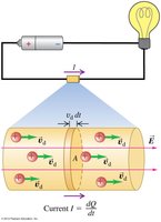
Drift Velocity and Current Density
Drift velocity () is the average velocity of charge carriers due to an electric field.
The current through a conductor can be expressed as , where:
= number of charge carriers per unit volume
= charge of each carrier
= cross-sectional area
= drift velocity
Current density (J) is the current per unit area: .
Resistivity and Conductivity
Resistivity () and Conductivity ()
Resistivity () is a material property that quantifies how strongly a material opposes the flow of electric current. It is defined as , where is the electric field and is the current density.
Conductivity () is the reciprocal of resistivity: .
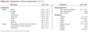
Resistivity of Materials
Different materials have different resistivities, which are typically measured at room temperature (20°C).
Metals have low resistivity, while insulators have high resistivity.
Substance | Resistivity () |
|---|---|
Silver | 1.47 × 10⁻⁸ |
Copper | 1.72 × 10⁻⁸ |
Glass | 1010 - 1014 |
Wood | 107 - 1010 |
Pure silicon (semiconductor) | 2.3 × 10³ |
Additional info: See image_6 for a more complete table. |
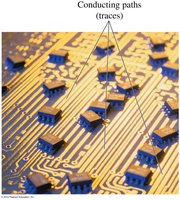
Applications: Circuit Boards and Nerve Conduction
Conducting paths on circuit boards are made from materials with low resistivity to ensure efficient current flow.
Nerve conduction in biological systems relies on the resistivity of axons and the insulating properties of myelin.

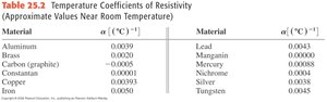
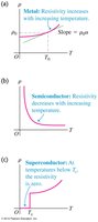
Temperature Dependence of Resistivity
For most conductors, resistivity increases with temperature: .
is the temperature coefficient of resistivity, which varies by material.
Semiconductors and superconductors exhibit different temperature dependencies.
Material | Temperature Coefficient (°C-1) |
|---|---|
Aluminum | 0.0039 |
Copper | 0.00393 |
Carbon (graphite) | -0.0005 |
Silver | 0.0038 |
Tungsten | 0.0045 |
Additional info: See image_9 for a more complete table. |
Theory of Metallic Conduction
In metals, resistivity is given by , where:
= mass of electron
= number density of electrons
= elementary charge
= mean free time between collisions
Ohm’s Law and Resistance
Ohm’s Law
Ohm’s law states that the current through a conductor between two points is directly proportional to the voltage across the two points, provided the temperature remains constant: .
The resistance of a conductor is , where is the length and is the cross-sectional area.
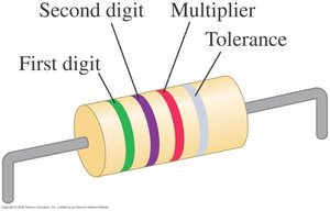
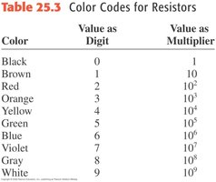
Resistor Color Codes
Resistors are color-coded to indicate their resistance value and tolerance.
The first two bands represent digits, the third is a multiplier, and the fourth (if present) indicates tolerance.
Tolerance indicates the precision of the resistor value.
Color | Digit | Multiplier |
|---|---|---|
Black | 0 | 1 |
Brown | 1 | 10 |
Red | 2 | 102 |
Orange | 3 | 103 |
Yellow | 4 | 104 |
Green | 5 | 105 |
Blue | 6 | 106 |
Violet | 7 | 107 |
Gray | 8 | 108 |
White | 9 | 109 |
Electromotive Force (EMF) and Circuits
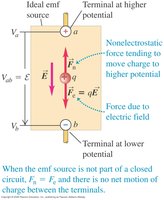
Electromotive Force (EMF)
An emf is a device or process that supplies energy to move charges through a circuit, maintaining a potential difference.
Common sources of emf include batteries and generators.
Despite its name, emf is not a force but a potential difference (measured in volts).
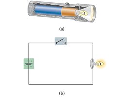
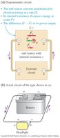
EMF in Open and Closed Circuits
In an open circuit, the emf source creates a potential difference but no current flows.
In a closed circuit, the emf source drives a current through the circuit.
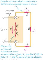
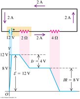
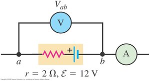
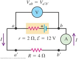
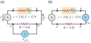
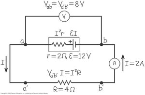
Internal Resistance
Real emf sources have internal resistance (), which reduces the terminal voltage when current flows.
The terminal voltage is .
The current in a circuit with internal resistance is , where is the external resistance.
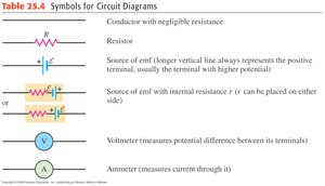
Circuit Symbols
Standard symbols are used in circuit diagrams for resistors, emf sources, voltmeters, and ammeters.
Potential Changes Around a Circuit
The sum of potential changes around a closed circuit loop is zero (Kirchhoff's loop rule).
Measuring Current and Voltage
Voltmeters and Ammeters
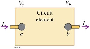
An ideal voltmeter has infinite resistance and is connected in parallel with the circuit element being measured.
An ideal ammeter has zero resistance and is connected in series with the circuit element being measured.
Example Circuit Measurements
In an open circuit, the ammeter reads 0 A and the voltmeter reads the emf value.
In a closed circuit, the ammeter reads the circuit current and the voltmeter reads the potential difference across the load.
Energy and Power in Electric Circuits
Power Delivered to a Circuit Element
The rate at which energy is delivered to a circuit element is .
For a resistor, .
Power Input and Output
The total power supplied by the emf source is .
Power dissipated in the internal resistance: .
Power dissipated in the external resistor: .
Conceptual Questions and Applications
Drift Speed in Wires of Different Diameters
When current flows from a larger-diameter wire to a smaller-diameter wire, the drift speed of electrons increases due to the reduced cross-sectional area.
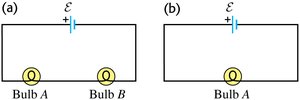
Bulb Brightness in Circuits
In a series circuit with identical bulbs, removing one bulb and completing the circuit increases the brightness of the remaining bulb, as the total resistance decreases and current increases.

Summary Table: Key Equations
Quantity | Equation |
|---|---|
Current | |
Current Density | |
Ohm's Law | |
Resistance | |
Power | |
Terminal Voltage |
Additional info: These notes provide a comprehensive overview of current, resistance, and emf, suitable for exam preparation in introductory college physics.
