Back
BackCurrent, Resistance, and Electromotive Force: Study Notes
Study Guide - Smart Notes
 Tailored notes based on your materials, expanded with key definitions, examples, and context.
Current, Resistance, and Electromotive Force
Introduction to Electric Circuits
Electric circuits are fundamental to modern technology, enabling the operation of devices from flashlights to computers. In a closed circuit, charges move continuously, transferring energy as they flow through components such as light bulbs. The amount of current entering and leaving a component remains constant, but the energy carried by the charges decreases as work is done (e.g., lighting a bulb).
Electric Current
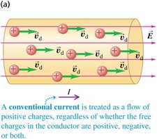
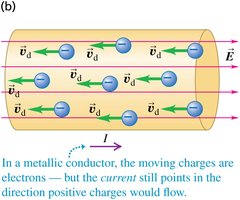
Electric current is defined as the motion of electric charge from one region to another. It is a scalar quantity, typically measured in amperes (A), where 1 ampere equals 1 coulomb per second.
Definition: The rate of flow of electric charge through a cross-section of a conductor.
Formula: , where is current, is the charge, and is the time interval.
Direction: By convention, current is considered the flow of positive charges, even though in metals, the actual charge carriers are electrons (negative charges).
Charge Carriers in Conductors
Conductors may contain various types of charge carriers. For example, in ionic solutions, both positive and negative ions contribute to the total current. The net current is the sum of the currents due to each type of charge carrier.
Example: In a sodium chloride solution, sodium ions (Na+) and chloride ions (Cl-) both move and carry current.

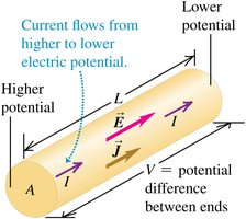
Current Density
Current density is a vector quantity that describes the amount of current flowing per unit area of a conductor. It is always in the direction of the electric field, regardless of the sign of the charge carriers.
Formula: , where is the number density of charge carriers, is the charge, and is the drift velocity.
Resistivity and Conductivity
Resistivity () is a material property that quantifies how strongly a material opposes the flow of electric current. Conductivity () is its reciprocal and measures how easily current flows.
Formula: , where is the electric field and is the current density.
Conductivity:
Resistivity and Temperature
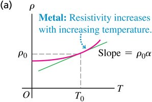
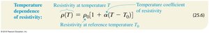
The resistivity of materials changes with temperature. For metals, resistivity increases with temperature, while for semiconductors, it decreases as more charge carriers become available at higher temperatures.
Metals:
Semiconductors: Resistivity decreases with increasing temperature.
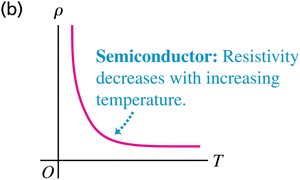
Superconductors: Below a critical temperature , resistivity drops abruptly to zero.
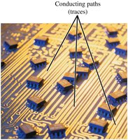
Applications: Circuit Boards and Resistivity
In electronic devices, circuit boards use materials with high resistivity as insulators to prevent unwanted current flow between conducting paths (traces), ensuring proper circuit operation.
Resistance and Ohm’s Law
Resistance () is a measure of how much a component opposes the flow of current. Ohm’s law relates the voltage (), current (), and resistance ($R$) in a conductor:
Ohm’s Law:
Unit: The unit of resistance is the ohm ().
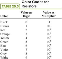
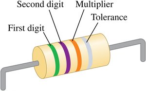
Resistor Identification: Resistors are color-coded for easy identification of their resistance values and tolerances.
Color | Value as Digit | Value as Multiplier |
|---|---|---|
Black | 0 | 1 |
Brown | 1 | 10 |
Red | 2 | 10^2 |
Orange | 3 | 10^3 |
Yellow | 4 | 10^4 |
Green | 5 | 10^5 |
Blue | 6 | 10^6 |
Violet | 7 | 10^7 |
Gray | 8 | 10^8 |
White | 9 | 10^9 |
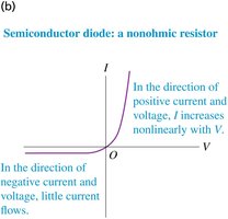
Ohmic and Nonohmic Resistors
Ohmic resistors obey Ohm’s law, showing a linear relationship between current and voltage. Nonohmic resistors, such as diodes, have a nonlinear current-voltage relationship.
Ohmic: (straight line on I-V graph)
Nonohmic: is not directly proportional to ; behavior may differ for positive and negative voltages.
Electromotive Force (emf) and Circuits
Electromotive force (emf) is the energy per unit charge supplied by a source, such as a battery, to move charges through a circuit. It is measured in volts (V) and is not an actual force, but a potential difference.
Definition: The work done per unit charge to move charge from lower to higher potential inside the source.
Symbol:
Unit: Volt (V), where

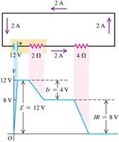
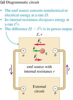
Internal Resistance of emf Sources
Real sources of emf have internal resistance (), which causes the terminal voltage to be less than the emf when current flows. The relationship is given by:
Formula:
Where: is the terminal voltage, is the current, is the internal resistance.

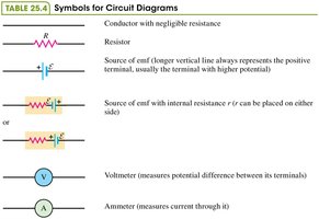
Circuit Diagrams and Symbols
Circuit diagrams use standardized symbols to represent components such as resistors, batteries, and measuring devices. Understanding these symbols is essential for analyzing and constructing circuits.
Symbol | Component |
|---|---|
—/\/\/\/— | Resistor |
—| |— | Source of emf (battery) |
—(A)— | Ammeter |
—(V)— | Voltmeter |
Potential Changes in a Circuit
As current flows around a circuit, the electric potential rises when passing through a source of emf and drops when passing through resistors. The total change in potential around a closed loop is zero, consistent with energy conservation.
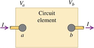
Energy and Power in Electric Circuits
Electric circuits transfer energy from sources to loads (e.g., bulbs, motors). The rate at which energy is transferred is called power ().
Formula:
Where: is the potential difference across the element, is the current through it.

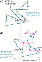
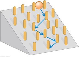
Metallic Conduction: The Drude Model
In metals, conduction electrons move freely through the crystal lattice, colliding with stationary positive ions. The motion is analogous to a ball rolling down an inclined plane and bouncing off obstacles, resulting in a net drift in the direction of the electric field.
Drift Velocity: The average velocity of electrons due to the electric field, superimposed on their random thermal motion.